Computers
Computer Parts
Custom PC Builder
DIY/ Maker
{$smarty.capture.menu}
Activity
Categories
Discussions
Computers
Computer Parts
Custom PC Builder
DIY/ Maker
Inland NANO Shield (Blue and Eco-friendly) - Micro Center
<main> <article class="userContent"> <h2 data-id="inland-nano-shield-(blue-and-eco-friendly)">Inland NANO Shield (Blue and Eco-friendly)</h2><div class="embedExternal embedImage display-large float-none"> <div class="embedExternal-content"> <a class="embedImage-link" href="https://us.v-cdn.net/6031942/uploads/XXN3UQRTDMWO/image.png" rel="nofollow noreferrer noopener ugc" target="_blank"> <img class="embedImage-img" src="https://us.v-cdn.net/6031942/uploads/XXN3UQRTDMWO/image.png" alt="image.png" height="379" width="407" loading="lazy" data-display-size="large" data-float="none"></img></a> </div> </div> <h2 data-id="overview">Overview </h2><p>
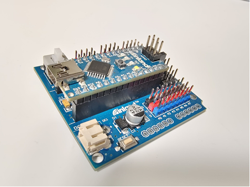
Nano is a tiny control board based on Arduino platform, which is deeply popular. </p><p>
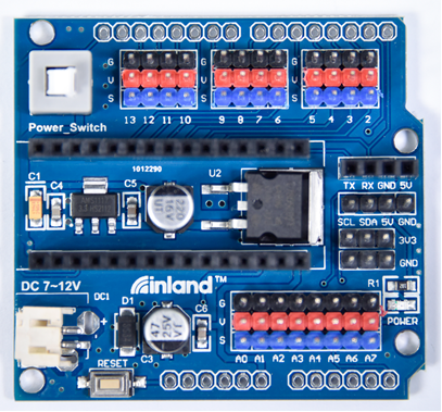
However, if want to connect several sensor modules to Nano , and connect external power, we need to use breadboard and a bunch of jumper wires, which is pretty inconvenient. We specially design this NANO shield, fully compatible with Nano. The NANO shield has brought out digital and analog pins of Nano into 3PIN headers (GND, 5V, Signal) with pin pitch of 2.54mm.</p><p>The NANO shield also leads out frequently-used communication pins, such as serial port communication and I2C communication. It’s greatly easy to connect Nano and other sensor modules.</p><p>It comes with a power indicator and a reset button as well. For external power, the NANO shield comes with a PH2.0-2P connector (input DC7-12V); a Power_Switch for power control. To supply power for other sensors, the NANO shield comes with a 3-way DC3.3V power output pin header with pin pitch of 2.54mm.</p><p>It comes with 4 fixing holes with a diameter of 3mm, so easy to mount on other devices.</p><div class="embedExternal embedImage display-large float-none"> <div class="embedExternal-content"> <a class="embedImage-link" href="https://us.v-cdn.net/6031942/uploads/CMJ6SKFQH6DE/dwdwe.jpg" rel="nofollow noreferrer noopener ugc" target="_blank"> <img class="embedImage-img" src="https://us.v-cdn.net/6031942/uploads/CMJ6SKFQH6DE/dwdwe.jpg" alt="dwdwe.jpg" height="1440" width="1920" loading="lazy" data-display-size="large" data-float="none"></img></a> </div> </div> <h2 data-id="features">Features </h2><p>1. Extends 12 digital pins into 3pin header</p><p>2. Extends 8 analog pins into 3pin header</p><p>3. Comes with a serial communication pin header (for Bluetooth module)</p><p>4. Comes with an I2C communication pin</p><p>5. Comes with 3-way DC 3.3V power output pin</p><p>6. Comes with a power indicator and a reset button</p><p>7. Comes with an external power connector(PH2.0-2P)and a control button</p><h2 data-id="technical-parameters">Technical Parameters </h2><ul><li>Voltage input: DC7-12V</li><li>Power connector: PH2.0-2P</li><li>Pin/Female header: 2.54mm</li><li>Fixing hole diameter: 3mm</li><li>Dimensions: 57mm*54mm*17mm</li><li>Weight: 20.4g</li></ul><h2 data-id="pinouts">PINOUTS</h2><div class="embedExternal embedImage display-large float-none"> <div class="embedExternal-content"> <a class="embedImage-link" href="https://us.v-cdn.net/6031942/uploads/P220KR7SGOLV/image.png" rel="nofollow noreferrer noopener ugc" target="_blank"> <img class="embedImage-img" src="https://us.v-cdn.net/6031942/uploads/P220KR7SGOLV/image.png" alt="image.png" height="391" width="665" loading="lazy" data-display-size="large" data-float="none"></img></a> </div> </div> <h2 data-id="use-method">Use Method</h2><p>We can use Nano as control board, separately connect 3 LED modules to D4~D6 3Pin interface. Then upload the test code to make LED flash one by one, achieving light flow effect.</p><h2 data-id="wiring-diagram">Wiring Diagram</h2><div class="embedExternal embedImage display-large float-none"> <div class="embedExternal-content"> <a class="embedImage-link" href="https://us.v-cdn.net/6031942/uploads/2SFMFSBBPJ6O/image.png" rel="nofollow noreferrer noopener ugc" target="_blank"> <img class="embedImage-img" src="https://us.v-cdn.net/6031942/uploads/2SFMFSBBPJ6O/image.png" alt="image.png" height="379" width="505" loading="lazy" data-display-size="large" data-float="none"></img></a> </div> </div> <h2 data-id="test-code">Test Code</h2><pre class="code codeBlock" spellcheck="false" tabindex="0">int BASE = 4; // I/O pin connected to the first LED int NUM = 3; //the number of LED void setup() { for (int i = BASE; i < BASE + NUM; i ++) { pinMode(i, OUTPUT); //set the digital I/O pin to output } } void loop() { for (int i = BASE; i < BASE + NUM; i ++) { digitalWrite(i, HIGH); //set the digital I/O pin output to "HIGH",gradually turn on LED delay(200); //delay } for (int i = BASE; i < BASE + NUM; i ++) { digitalWrite(i, LOW); //set the digital I/O pin output to "LOW",gradually turn off LED delay(200); //delay } } </pre><h2 data-id="test-result">Test Result</h2><p>Upload well the code to Nano shield, then press down Power_Switch, the LED module will flash one by one.</p> </article> </main>