Inland Electronic Parts DIY Kit For OTTO Robot Maker

Contents
1. Who is Otto DIY ?
2. Kit List
3. 3D Printing Parts
4. Print Settings
5. Build Your Own Otto Robot:
- Step1: Check Your Parts From Bottom to Top
- Step2: Foot Servos Assembly
- Step3: Fix Servos to Body
- Step4: Fix Legs to Body
- Step5: Fix Foot to Legs
- Step6: Head Assembly
- Step7: Electric Connection
- Step8: Snap the Head
- Step9: Arduino Programming
6. Resources
1. Who is Otto DIY ?
Otto is an interactive robot that anyone can make! It is completely open source, Arduino compatible and 3D printable.
Otto is able to walk, dance, make sounds and avoid obstacles. His small body is in the assembled size, with simple structure. The shelf parts are designed using 3D printer, simple electronics connections (almost no welding required), and basic coding skills.
Otto is designed using Autodesk 123D Design software. No need technical knowledge, perfect for beginners. You are able to modify it or even recreate them to make you own Otto robot and then share to the world!
2. Kit List
The kit includes everything you need to build your Otto in 1 hour:
NO SOLDERING REQUIRED!
Note: the print parts are Not Included!


3. 3D Printing Parts
And then you only need to 3D print 6 parts in total:
- 3D printed head
- 3D printed body
- 3D printed leg x2
- 3D printed right foot
- 3D printed left foot
For the 3D printing parts, you can print them out with 3D printer.
That's all simple! Download all .stl files here in Thingiverse. If you do not have a 3d printer, you can always use services like 3dhubs.com or local maker spaces.
4. Print Settings
Otto is very well designed for 3D printing, so won’t give you trouble if you follow this common parameters:
- Recommended to use a FDM 3D printer with PLA material.
- No need supports or rafts at all.
- Resolution: 0.15mm
- Fill density: 20%
Notes:
You can print individually piece by piece to match the colors of the original design or optionally print all at the same time in an area of 14cm x 14cm.
For slicing and generating the g code for the machine free slicer software like Cura or FlashPrint that comes with the FlashForge Finder 3D printer that we are using (If you are outsourcing the printing, no need to worry about it)
After printing, you will need to clean a little bit the legs and feet areas that fix the motors.
5. Build Your Own Otto Robot:
- Step 1: Check Your Parts From Bottom to Top

Print the attached .pdf instructions manual for convenience:
OTTO-DIY-Instruction-Manual
- Step 2: Foot Servos Assembly

Put the micro servo inside feet and then push it inside, if is to hard maybe need to clean more the area with a cutter.
Is very important to check that the servo is able to rotate at 180 degrees to each side.
After checking the movement, use only the small screw to fix it.
Same process for the other foot.

- Step 3: Fix Servos to Body
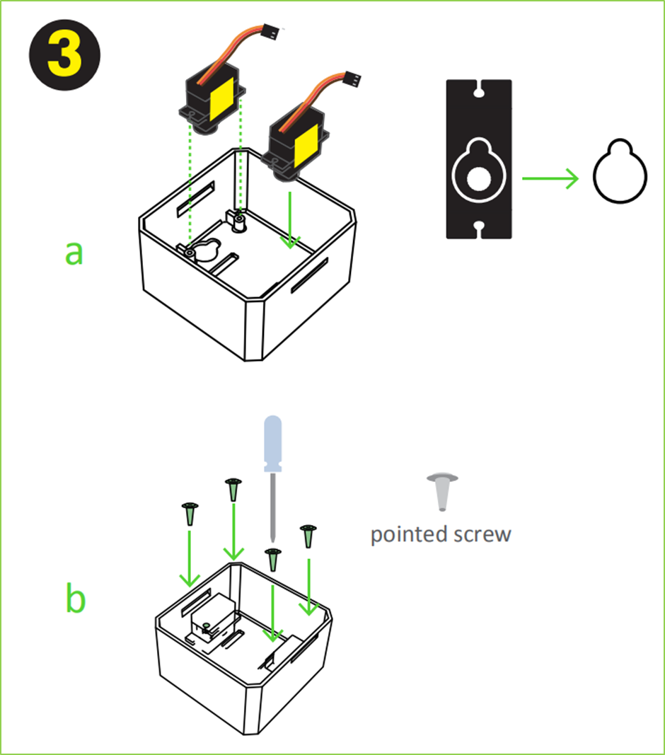
Take the other 2 micro servos put them in the defined locations in the 3D printed body, and fix them only with screws.

Connect the legs to the hub of the micro servo, important like the foot servos, you must check the legs are able to rotate 180 degrees each side respect to the body.
After verifying the alignment, fix them using the small screws to the hole inside the leg.

Taking care of the cables as showed in the illustration, you should put the cables inside the slots of the body passing through the hole of the legs.
Once they are in right position, use the pointed screws to fix them from the back.

Start from the ultrasound sensor is important to pull out the eyes to the limit. Then put the Arduino nano in the shield, optionally you can weld the positive cable of battery holder to Vin in the board and negative cable to any GND.
Insert diagonally the both boards together facing the USB conector to the hole in the 3D printed head, then use the pointed screws to fix it.
- Step7: Electric Connection
Prepare the jumper cables, buzzer, and switch.
Then follow the diagram pins numbers and make sure to put them in the right position.


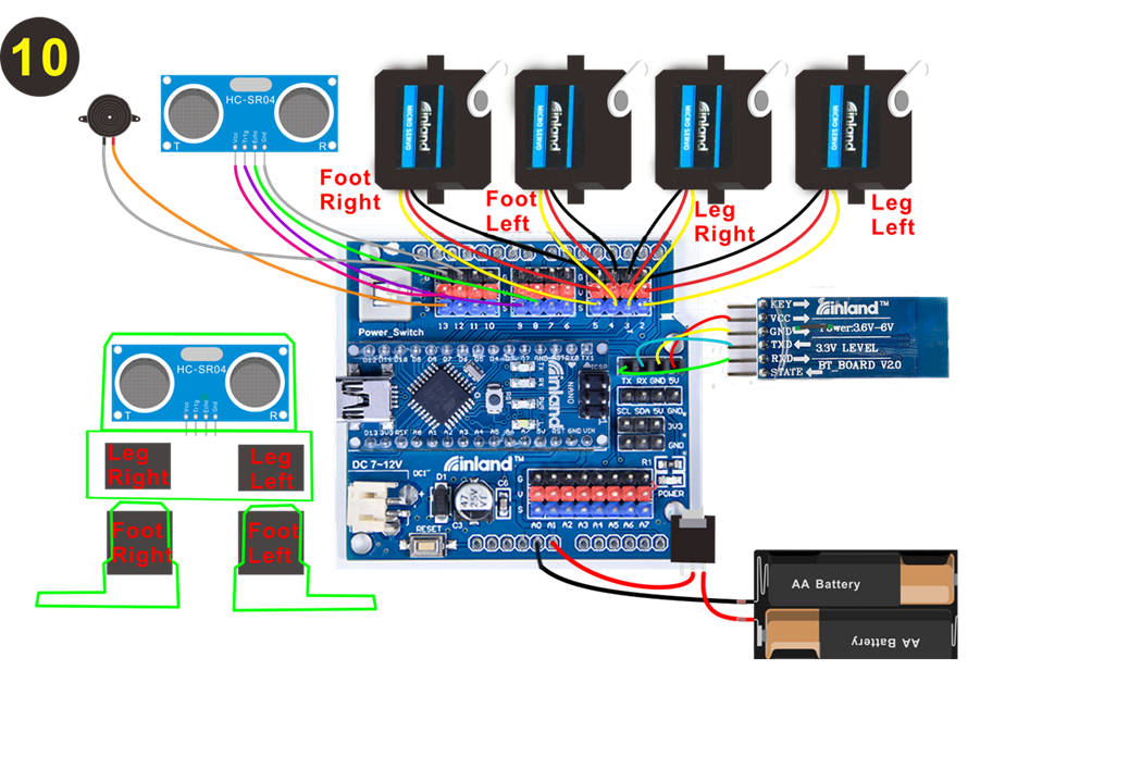
Special note:
1. When connecting the Bluetooth module, CANNOT directly plug into the shield. Or else, the space is not enough, should connect the Bluetooth module to the shield with male-to-female jumper wires. The jumper wires are Not Included in the kit list.
2. When connecting well all the components and uploading the code, CANNOT press the button welded to battery case, that is, CANNOT supply the power; otherwise, code upload fails.
Install the battery box The positive pole is connected to 5V, and the negative pole is connected to GND (Note: need soldering)

The Head has snap feature, take care of the cables and close it. Congrats!

- Step 9: Arduino Programming

For the coding part you will need to:
1. Download and install Arduino softwareIDE:
https://www.arduino.cc/en/Main/Software
2. Copy all libraries to C:/Users/user/Documents/Arduino/libraries (or wherever your library folder is installed)
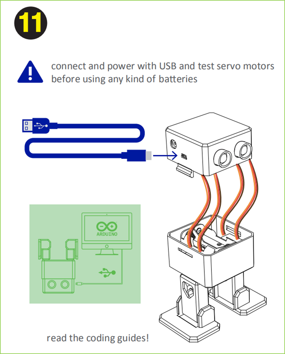
3. Connect your Otto through USB (your computer should install the drivers)
4. Finally open OTTO_smooth_criminal.ino code and upload to your Arduino Nano for dancing Otto mode.
5. Try OTTO_avoid.ino for obstacle avoidance
More codes in https://github.com/OttoDIY/
You can always try different codes from the same Github repository to use the ultrasound to avoid obstacles or detect objects and the buzzer to make sounds. Include all main moves very easy to adjust speed, number of times and direction.

Special note:
This OTTO kit is similar to inland Frog Robot for Arduino Graphical Programming kit(KS0446).
This OTTO kit contains a HC-06 Bluetooth module, using Bluetooth 2.0, only compatible with Android phone. But frog robot kit contains a HM-10 Bluetooth module, compatible with both Android and iOS phone.
When using, as long as the Bluetooth module is not involved, these two product kits can use the common source code.
Check relevant info of frog robot kit from the link:
https://wiki.inland.com/KS0446_inland_Frog_Robot_for_Arduino_Graphical_Programming
6. Resources
Otto website:https://www.ottodiy.com/
Tutorial from: https://www.thingiverse.com/thing:1568652/#files
More Codes from: https://github.com/OttoDIY/DIY