Project 1: Hello World
Introduction
As for starters, we will begin with something simple. In this project, you only need an Arduino
and a USB cable to start the "Hello World!" experiment. This is a communication test of your
Arduino and PC, also a primer project for you to have your first try of the Arduino world!
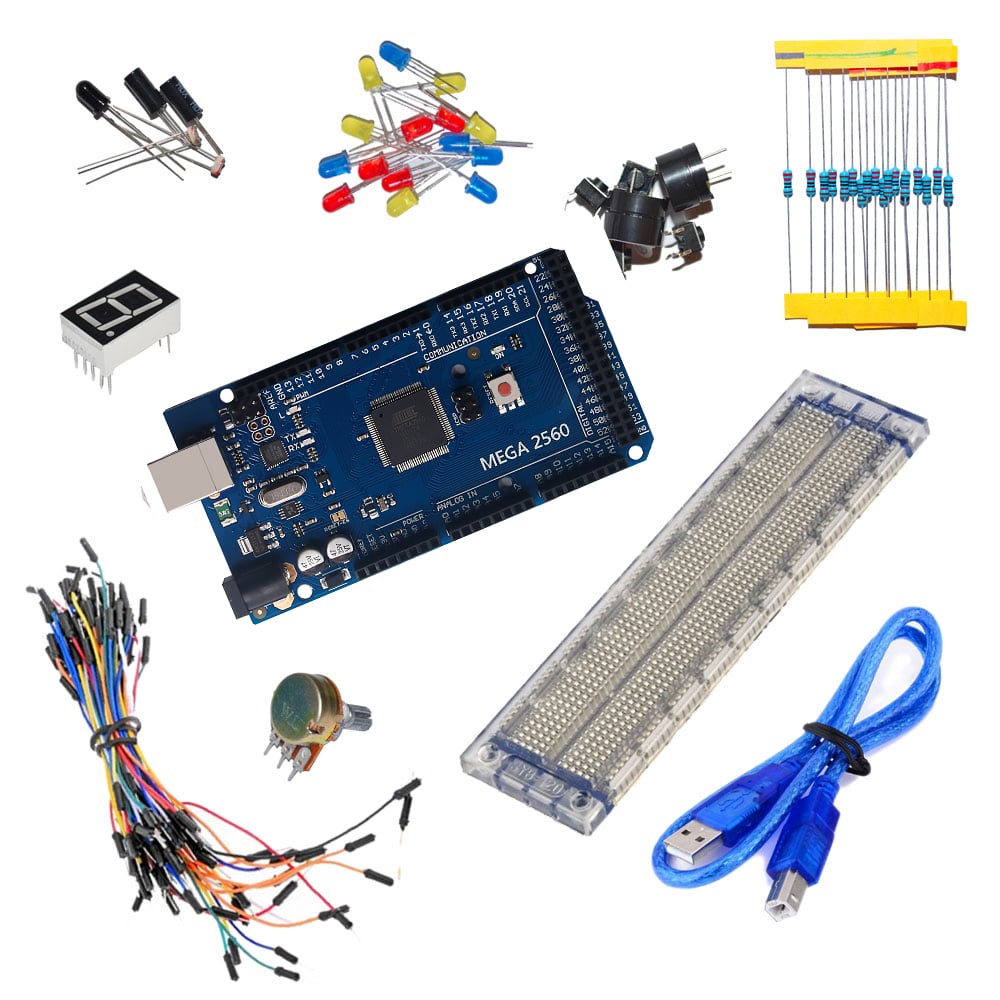
Hardware required
Arduino board *1
USB cable *1
Sample program
After installing driver for Arduino, let's open Arduino software and compile code that enables
Arduino to print "Hello World!" under your instruction. Of course, you can compile code for
Arduino to continuously echo "Hello World!" without instruction. A simple If () statement will do
the instruction trick. With the onboard LED connected to pin 13, we can instruct the LED to blink
first when Arduino gets an instruction and then print "Hello World!”.
//////////////////////////////////////////////////////////
int val;//define variable val
int ledpin=13;// define digital interface 13
void setup()
{
Serial.begin(9600);// set the baud rate at 9600 to match the software set up. When connected to
a specific device, (e.g. bluetooth), the baud rate needs to be the same with it.
pinMode(ledpin,OUTPUT);// initialize digital pin 13 as output. When using I/O ports on an
Arduino, this kind of set up is always needed.
}
void loop()
{
val=Serial.read();// read the instruction or character from PC to Arduino, and assign them to
Val.
if(val=='R')// determine if the instruction or character received is “R”.
{ // if it’s “R”,
digitalWrite(ledpin,HIGH);// set the LED on digital pin 13 on.
delay(500);
digitalWrite(ledpin,LOW);// set the LED on digital pin 13 off.
delay(500);
Serial.println("Hello World!");// display“Hello World!”string.
}
}
////////////////////////////////////////////////////////////////
Result
Click serial port monitor,Input R,LED 13 will blink once,PC will receive information from
Arduino: Hello World
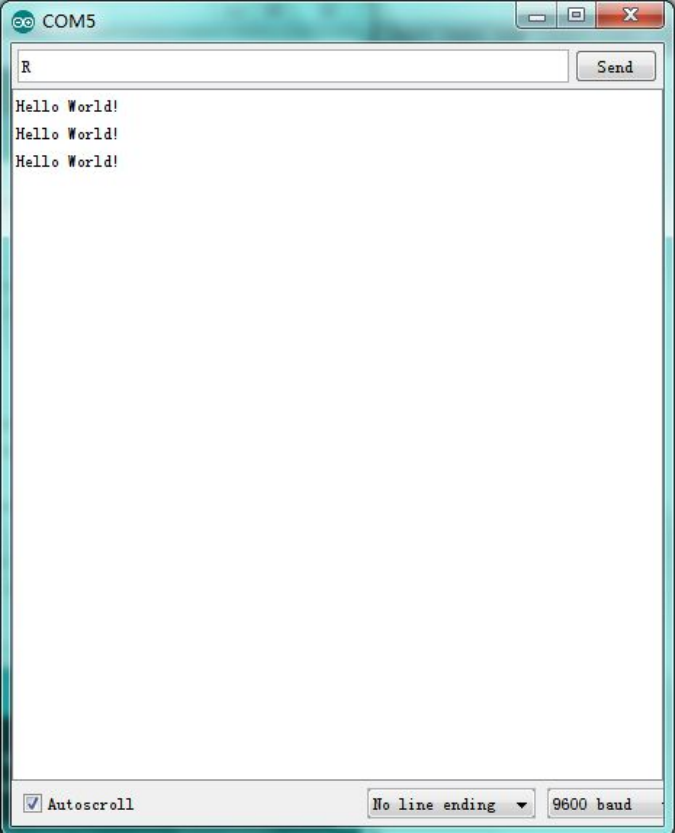
After you choosing the right port,the experiment should be easy for you!
Project 2: LED blinking
Introduction
Blinking LED experiment is quite simple. In the "Hello World!" program, we have come across
LED. This time, we are going to connect an LED to one of the digital pins rather than using
LED13, which is soldered to the board. Except an Arduino and an USB cable, we will need extra
parts as below:
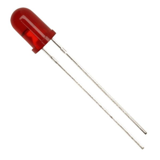
Hardware required
Red M5 LED*1
220Ω resistor*1
Breadboard*1
Breadboard jumper wires
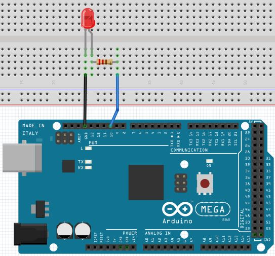
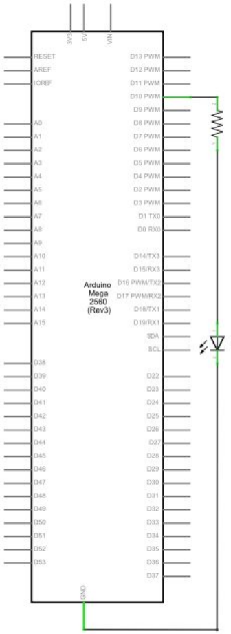
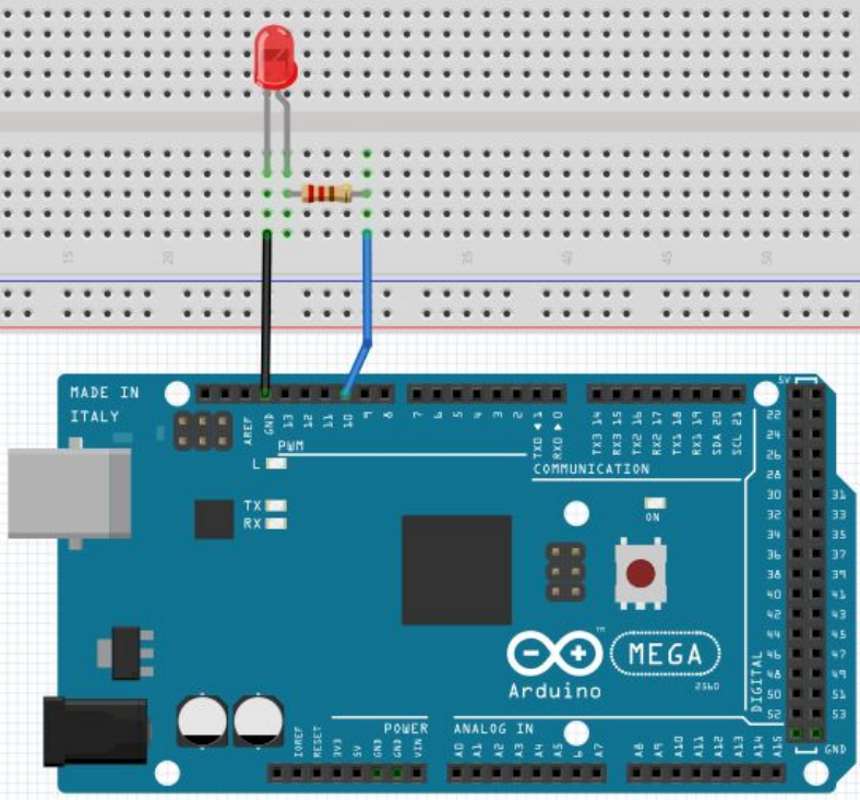
Circuit connection
We follow below diagram from the experimental schematic link. Here we use digital pin 10. We
connect LED to a 220 ohm resistor to avoid high current damaging the LED
Sample program
//////////////////////////////////////////////////////////
int ledPin = 10; // define digital pin 10.
void setup()
{
pinMode(ledPin, OUTPUT);// define pin with LED connected as output.
}
void loop()
{
digitalWrite(ledPin, HIGH); // set the LED on.
delay(1000); // wait for a second.
digitalWrite(ledPin, LOW); // set the LED off.
delay(1000); // wait for a second
}
//////////////////////////////////////////////////////////
Result
After downloading this program, in the experiment, you will see the LED connected to pin 10
turning on and off, with an interval approximately one second.
The blinking LED experiment is now completed. Thank you!
Project 3: PWM light control
Introduction
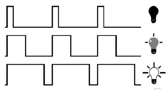
PWM, short for Pulse Width Modulation, is a technique used to encode analog signal level into
digital ones. A computer cannot output analog voltage but only digital voltage values such as 0V
or 5V. So we use a high resolution counter to encode a specific analog signal level by modulating
the duty cycle of PMW. The PWM signal is also digitalized because in any given moment, fully
on DC power supply is either 5V (ON), or 0V (OFF). The voltage or current is fed to the analog
load (the device that uses the power) by repeated pulse sequence being ON or OFF. Being on, the
current is fed to the load; being off, it's not. With adequate bandwidth, any analog value can be
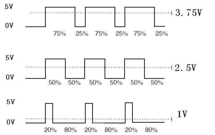
encoded using PWM. The output voltage value is calculated via the on and off time. Output
voltage = (turn on time/pulse time) * maximum voltage value
PWM has many applications: lamp brightness regulating, motor speed regulating, sound making,
etc.
The following are the three basic parameters of PMW:
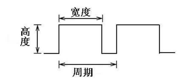
1. The amplitude of pulse width (minimum / maximum)
2. The pulse period (The reciprocal of pulse frequency in 1 second)
3. The voltage level(such as:0V-5V)
There are 6 PMW interfaces on Arduino, namely digital pin 3, 5, 6, 9, 10, and 11. In previous
experiments, we have done "button-controlled LED", using digital signal to control digital pin,
also one about potentiometer. This time, we will use a potentiometer to control the brightness of
the LED.
Hardware required
Variable resistor*1
Red M5 LED*1
220Ω resistor*1
Breadboard*1
Breadboard jumper wires
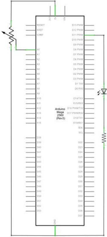
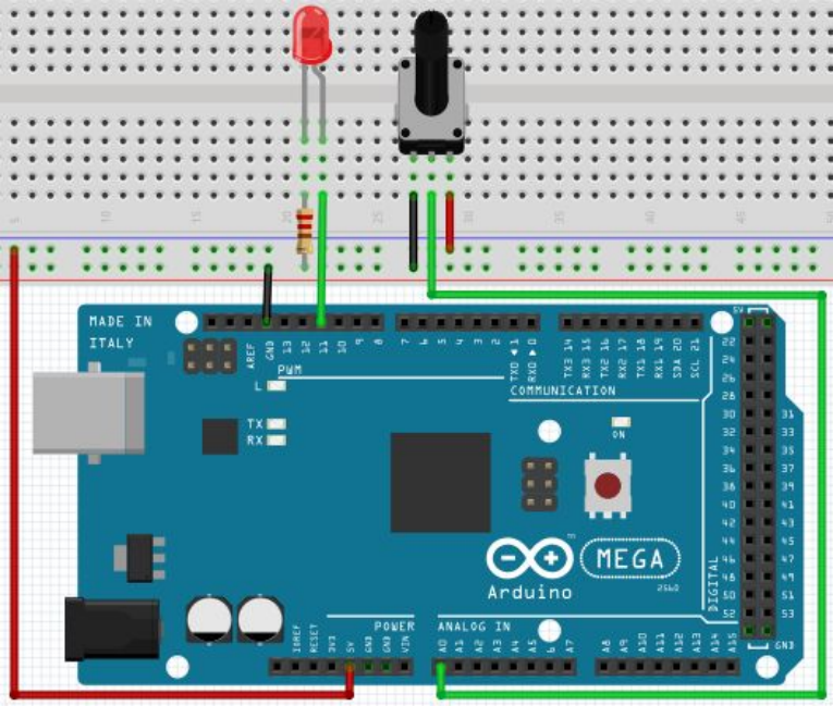
Circuit connection
Width
Cycle
Level
10
The input of potentiometer is analog, so we connect it to analog port, and LED to PWM port.
Different PWM signal can regulate the brightness of the LED
Sample program
In the program compiling process, we will use the analogWrite (PWM interface, analog value)
function. In this experiment, we will read the analog value of the potentiometer and assign the
value to PWM port, so there will be corresponding change to the brightness of the LED. One final
part will be displaying the analog value on the screen. You can consider this as the "analog value
reading" project adding the PWM analog value assigning part. Below is a sample program for
your reference.
//////////////////////////////////////////////////////////
int potpin=0;// initialize analog pin 0
int ledpin=11;//initialize digital pin 11(PWM output)
int val=0;// Temporarily store variables' value from the sensor
void setup()
{
pinMode(ledpin,OUTPUT);// define digital pin 11 as “output”
Serial.begin(9600);// set baud rate at 9600
// attention: for analog ports, they are automatically set up as “input”
}
void loop()
{
val=analogRead(potpin);// read the analog value from the sensor and assign it to val
Serial.println(val);// display value of val
analogWrite(ledpin,val/4);// turn on LED and set up brightness(maximum output of PWM is 255)
delay(10);// wait for 0.01 second
}
//////////////////////////////////////////////////////////
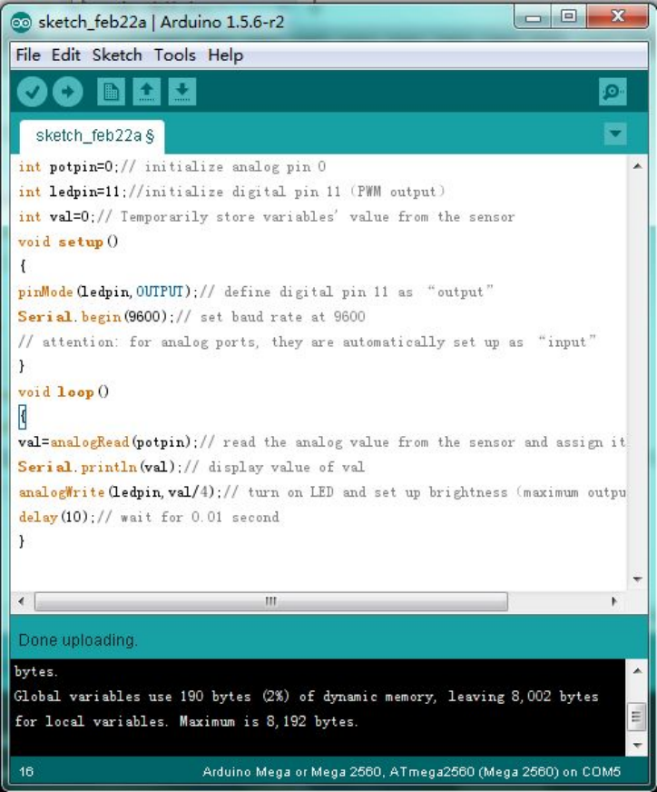
Result
After downloading the program, when we rotate the potentiometer knob, we can see changes of
the displaying value, also obvious change of the LED brightness on the breadboard.
*******************************************************************************
Project 4: Traffic light
Introduction
In the previous program, we have done the LED blinking experiment with one LED. Now, it’s
time to up the stakes and do a bit more complicated experiment-traffic lights. Actually, these two
experiments are similar. While in this traffic lights experiment, we use 3 LEDs with different
color other than 1 LED.
Hardware required
Arduino board *1
USB cable *1
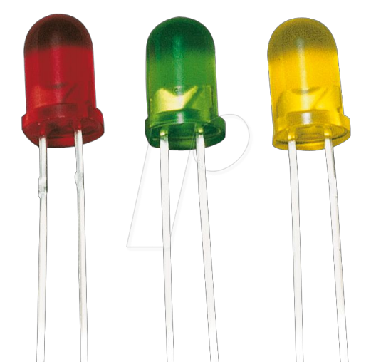
Red M5 LED*1
Yellow M5 LED*1
Green M5 LED*1
220Ω resistor *3
Breadboard*1
Breadboard jumper wires
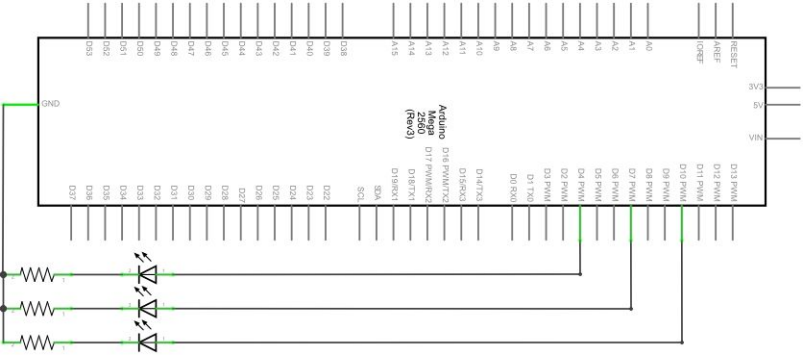
Circuit connection
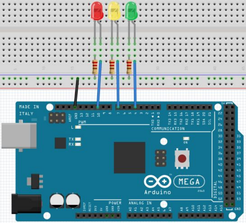
Sample program
Since it is a simulation of traffic lights, the blinking time of each LED should be the same with
those in traffic lights system. In this program, we use Arduino delay () function to control delay
time, which is much simpler than C language.
//////////////////////////////////////////////////////////
int redled =10; // initialize digital pin 8.
int yellowled =7; // initialize digital pin 7.
int greenled =4; // initialize digital pin 4.
void setup()
{
pinMode(redled, OUTPUT);// set the pin with red LED as “output”
pinMode(yellowled, OUTPUT); // set the pin with yellow LED as “output”
pinMode(greenled, OUTPUT); // set the pin with green LED as “output”
}
void loop()
{
digitalWrite(greenled, HIGH);//// turn on green LED
delay(5000);// wait 5 seconds
digitalWrite(greenled, LOW); // turn off green LED
for(int i=0;i<3;i++)// blinks for 3 times
{
delay(500);// wait 0.5 second
digitalWrite(yellowled, HIGH);// turn on yellow LED
delay(500);// wait 0.5 second
digitalWrite(yellowled, LOW);// turn off yellow LED
}
delay(500);// wait 0.5 second
digitalWrite(redled, HIGH);// turn on red LED
delay(5000);// wait 5 second
digitalWrite(redled, LOW);// turn off red LED
}
//////////////////////////////////////////////////////////
Result
When the uploading process is completed, we can see traffic lights of our own design.
Note: this circuit design is very similar with the one in LED chase effect.
The green light will be on for 5 seconds, and then off., followed by the yellow light blinking for 3
times, and then the red light on for 5 seconds, forming a cycle. Cycle then repeats.
Experiment is now completed, thank you.
*******************************************************************************