
Introduction
Relay Shield employs high quality relay with four channels input and output. It can be connected to 250V/10A AC element or 24V/10A DC element to the maximum, therefore, it can be used to control lights, motors, etc. The modularized design makes it easy to connect to Arduino expansion board. The output state of the relay is shown by a LED for the convenience of actual application.
Specification
- Control signal: TTL voltage
- Active at HIGH level
- Rated load:
10A 250VAC
10A 125VAC
10A 30DC
10A 28VDC
- Rated Through-current: 10A(NO) 5A(NC)
- Max Switching Voltage: 250VAC 30VDC
- Contact actuation time: ﹤10ms
- Definition of module pins:
i) Pin 1- Pin 4----Controlling end
ii) Power supply (VCC)
iii) Ground (GND)
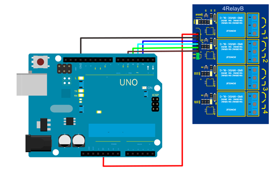
Connection Diagram
Sample Code
int BASE = 2 ;  // I/O pin connected to the first relay
int NUM = 4;   //total number of all relays
void setup()
{
  for (int i = BASE; i < BASE + NUM; i ++)
  {
    pinMode(i, OUTPUT);   //set digital I/O pin as output
  }
}
void loop()
{
  for (int i = BASE; i < BASE + NUM; i ++)
  {
    digitalWrite(i, LOW);    //set digital I/O pin as ‘low’, i.e. turning off the relay gradually
 delay(200);        //delay
  }
  for (int i = BASE; i < BASE + NUM; i ++)
  {
    digitalWrite(i, HIGH);    // set digital I/O pin as ‘high’, i.e. turning on the relay gradually
delay(200);        //delay
  }
}