Computers
Computer Parts
Custom PC Builder
DIY/ Maker
{$smarty.capture.menu}
Activity
Categories
Discussions
Computers
Computer Parts
Custom PC Builder
DIY/ Maker
Inland ESP8266 Starter Kit - Micro Center
<main> <article class="userContent"> <h2 data-id="inland-esp8266-starter-kit"><strong>Inland ESP8266 Starter Kit</strong></h2><div class="embedExternal embedImage display-medium float-none"> <div class="embedExternal-content"> <a class="embedImage-link" href="https://us.v-cdn.net/6031942/uploads/GYA88596EN17/image.png" rel="nofollow noreferrer noopener ugc" target="_blank"> <img class="embedImage-img" src="https://us.v-cdn.net/6031942/uploads/GYA88596EN17/image.png" alt="image.png" height="774" width="941" loading="lazy" data-display-size="medium" data-float="none"></img></a> </div> </div> <h2 data-id="contents"><strong>Contents</strong></h2><h3 data-id="1.-description"><strong>1. Description</strong></h3><h3 data-id="2.-component-list"><strong>2. Component List</strong></h3><h3 data-id="3.-installing-driver"><strong>3. Installing Driver</strong></h3><h3 data-id="4.-projects"><strong>4. Projects</strong></h3><ul><li><strong>Remotely Controlling LED On/Off Via Wi-Fi</strong></li><li><strong>Burning Firmware</strong></li><li><strong>Station Mode</strong></li><li><strong>Softap Mode</strong></li></ul><p></p><p><br></p><h2 data-id="1.-description-1">1. Description</h2><p>
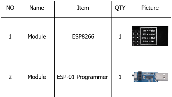
This kit contains the common components: resistors with different resistance values, different colors LEDs, buttons, and IR receiving components. It is compatible with various microcontrollers and Raspberry Pi. An ESP8266 module and an ESP-01 Programmer module are included. We can build a platform with this two modules and shield, which can help us control external devices via WIFI or send test data to PC. In order to have a better understanding, we make an experiment with components, and remotely control LED on/off via Wi-Fi. </p><p>For using easily, we provide self-compiled firmware. The firmware is server mode. Specific information as shown below:</p><h3 data-id="module-working-mode"><strong>Module Working Mode</strong></h3><p>Work in mode:3</p><h3 data-id="softap-mode"><strong>Softap mode</strong></h3><p>softAP SSID:KeyesWifi_A password:KeyesWifi</p><p>softAP IP:192.168.2.1</p><p>softAP_server IP:192.168.2.1</p><h3 data-id="station-mode"><strong>Station mode</strong></h3><p>station SSID:KeyesWifi_S password:KeyesWifi</p><p>station IP: router automatically assigns</p><p>station_server IP: router automatically distributes port:8080
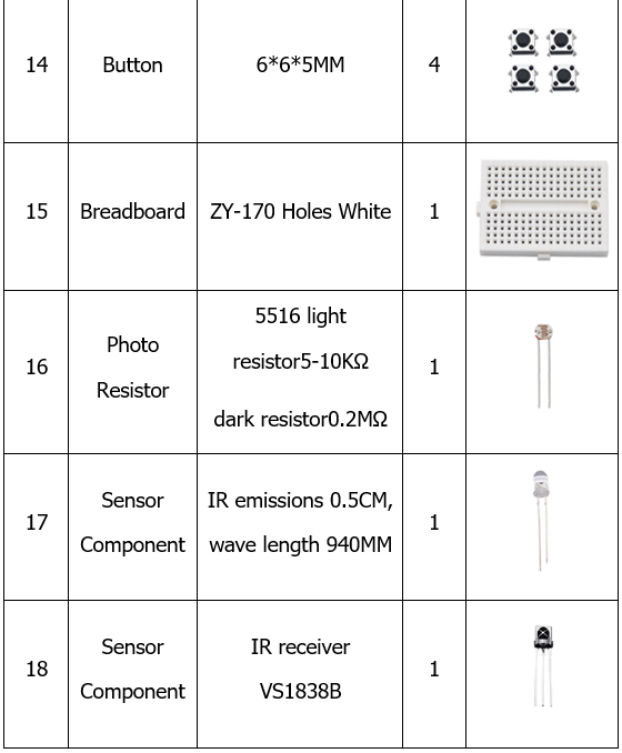
</p><p> </p><h2 data-id="2.-component-list-1">2. Component List</h2><div class="embedExternal embedImage display-large float-none"> <div class="embedExternal-content"> <a class="embedImage-link" href="https://us.v-cdn.net/6031942/uploads/ZRX07GA9H9QR/image.png" rel="nofollow noreferrer noopener ugc" target="_blank"> <img class="embedImage-img" src="https://us.v-cdn.net/6031942/uploads/ZRX07GA9H9QR/image.png" alt="image.png" height="317" width="560" loading="lazy" data-display-size="large" data-float="none"></img></a> </div> </div> <div class="embedExternal embedImage display-large float-none"> <div class="embedExternal-content"> <a class="embedImage-link" href="https://us.v-cdn.net/6031942/uploads/2LLR7L0Z60HK/image.png" rel="nofollow noreferrer noopener ugc" target="_blank"> <img class="embedImage-img" src="https://us.v-cdn.net/6031942/uploads/2LLR7L0Z60HK/image.png" alt="image.png" height="799" width="560" loading="lazy" data-display-size="large" data-float="none"></img></a> </div> </div> <div class="embedExternal embedImage display-large float-none"> <div class="embedExternal-content"> <a class="embedImage-link" href="https://us.v-cdn.net/6031942/uploads/7SFQ8GDXRQCV/image.png" rel="nofollow noreferrer noopener ugc" target="_blank"> <img class="embedImage-img" src="https://us.v-cdn.net/6031942/uploads/7SFQ8GDXRQCV/image.png" alt="image.png" height="856" width="558" loading="lazy" data-display-size="large" data-float="none"></img></a> </div> </div> <div class="embedExternal embedImage display-large float-none"> <div class="embedExternal-content"> <a class="embedImage-link" href="https://us.v-cdn.net/6031942/uploads/HS2UN8LNCKRA/image.png" rel="nofollow noreferrer noopener ugc" target="_blank"> <img class="embedImage-img" src="https://us.v-cdn.net/6031942/uploads/HS2UN8LNCKRA/image.png" alt="image.png" height="678" width="560" loading="lazy" data-display-size="large" data-float="none"></img></a> </div> </div> <h2 data-id="3.-installing-driver-1"><strong>3. Installing Driver</strong></h2><p>We need to install driver for ESP-01 Programmer module. The USB serial port chip CH340G is used in ESP-01 Programmer module. So we need to install driver compatible with CH340G.</p><p>Connect ESP-01 Programmer to computer. For Win10 system, the computer automatically installs the driver, click Computer-Properties-Device Manager, as shown below.</p><div class="embedExternal embedImage display-medium float-none"> <div class="embedExternal-content"> <a class="embedImage-link" href="https://us.v-cdn.net/6031942/uploads/O8FBBTM0P6MK/image.png" rel="nofollow noreferrer noopener ugc" target="_blank"> <img class="embedImage-img" src="https://us.v-cdn.net/6031942/uploads/O8FBBTM0P6MK/image.png" alt="image.png" height="516" width="709" loading="lazy" data-display-size="medium" data-float="none"></img></a> </div> </div> <p>For other systems, connect Esp-01 Programmer Module to PC, and click Computer-Properties-Device manager, as shown below:</p><div class="embedExternal embedImage display-medium float-none"> <div class="embedExternal-content"> <a class="embedImage-link" href="https://us.v-cdn.net/6031942/uploads/RBXDR1XI9V0C/image.png" rel="nofollow noreferrer noopener ugc" target="_blank"> <img class="embedImage-img" src="https://us.v-cdn.net/6031942/uploads/RBXDR1XI9V0C/image.png" alt="image.png" height="516" width="709" loading="lazy" data-display-size="medium" data-float="none"></img></a> </div> </div> <p>
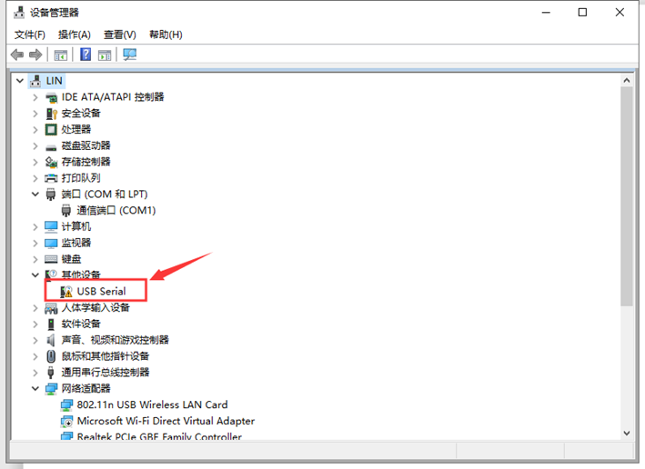
Click USB serial to install the driver, as shown below</p><div class="embedExternal embedImage display-medium float-none"> <div class="embedExternal-content"> <a class="embedImage-link" href="https://us.v-cdn.net/6031942/uploads/CVEX8BFQKCHE/image.png" rel="nofollow noreferrer noopener ugc" target="_blank"> <img class="embedImage-img" src="https://us.v-cdn.net/6031942/uploads/CVEX8BFQKCHE/image.png" alt="image.png" height="516" width="709" loading="lazy" data-display-size="medium" data-float="none"></img></a> </div> </div> <p>Enter the following interface, as shown below.</p><div class="embedExternal embedImage display-medium float-none"> <div class="embedExternal-content"> <a class="embedImage-link" href="https://us.v-cdn.net/6031942/uploads/H2QNJXVQSXCZ/image.png" rel="nofollow noreferrer noopener ugc" target="_blank"> <img class="embedImage-img" src="https://us.v-cdn.net/6031942/uploads/H2QNJXVQSXCZ/image.png" alt="image.png" height="516" width="709" loading="lazy" data-display-size="medium" data-float="none"></img></a> </div> </div> <p>Find usb_ch341_3.1.2009.06 folder</p><div class="embedExternal embedImage display-medium float-none"> <div class="embedExternal-content"> <a class="embedImage-link" href="https://us.v-cdn.net/6031942/uploads/A3TWTTK0O2O4/image.png" rel="nofollow noreferrer noopener ugc" target="_blank"> <img class="embedImage-img" src="https://us.v-cdn.net/6031942/uploads/A3TWTTK0O2O4/image.png" alt="image.png" height="516" width="709" loading="lazy" data-display-size="medium" data-float="none"></img></a> </div> </div> <p>Click “next step” to start installing.</p><div class="embedExternal embedImage display-medium float-none"> <div class="embedExternal-content"> <a class="embedImage-link" href="https://us.v-cdn.net/6031942/uploads/1I7V70JE5C71/image.png" rel="nofollow noreferrer noopener ugc" target="_blank"> <img class="embedImage-img" src="https://us.v-cdn.net/6031942/uploads/1I7V70JE5C71/image.png" alt="image.png" height="476" width="591" loading="lazy" data-display-size="medium" data-float="none"></img></a> </div> </div> <p>Finish installing, click to “close”</p><p>
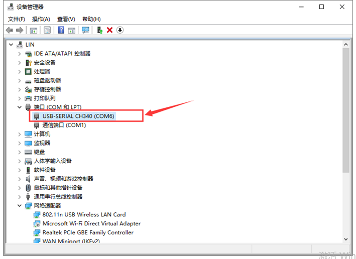
The driver is now installed. Click Computer-Properties-Device Manager, as shown below:</p><div class="embedExternal embedImage display-medium float-none"> <div class="embedExternal-content"> <a class="embedImage-link" href="https://us.v-cdn.net/6031942/uploads/FIHINBJQC2J8/image.png" rel="nofollow noreferrer noopener ugc" target="_blank"> <img class="embedImage-img" src="https://us.v-cdn.net/6031942/uploads/FIHINBJQC2J8/image.png" alt="image.png" height="516" width="709" loading="lazy" data-display-size="medium" data-float="none"></img></a> </div> </div> <p></p><p><br></p><p><br></p><h2 data-id="4.-projects-1">4. Projects</h2><p><br></p><h2 data-id="remotely-controlling-led-onoff-via-wi-fi">Remotely Controlling LED On/Off Via Wi-Fi</h2><h3 data-id="description">Description</h3><p>In the experiment, we connect to the ESP8266 module to wireless network, and then can send instructions to the ESP8266 module from the upper computer in the remote or local area network. After receiving the instruction, the ESP8266 module can control the external LED to turn on and off.</p><p> </p><p> </p><h3 data-id="experiment-equipment"><strong>Experiment Equipment</strong></h3><ul><li>ESP8266 module * 1</li><li> ESP-01 Programmer Module * 1</li><li> ESP-01 Breakout Board * 1</li><li> LED * 1</li><li> 220Ω resistor * 1</li><li> Breadboard * 1</li><li> Several male to female Dupont lines</li><li> Several DuPont Lines</li><li> 3.3V power supply (included)</li></ul><h3 data-id="burning-firmware">Burning Firmware</h3><p>First, we need to burn firmware in the ESP-01 Programmer module. The burning method is shown below:</p><ol><li> Switch the ESP-01 Programmer module to Uart Download, insert the ESP8266 module into the ESP-01 Programmer module, connect ESP-01 Programmer module to the computer USB interface.</li><li> Open “FLASH_DOWNLOAD_TOOL”, configure as shown below, upload firmware.</li></ol><div class="embedExternal embedImage display-small float-none"> <div class="embedExternal-content"> <a class="embedImage-link" href="https://us.v-cdn.net/6031942/uploads/BVTBZSUTB3NA/image.png" rel="nofollow noreferrer noopener ugc" target="_blank"> <img class="embedImage-img" src="https://us.v-cdn.net/6031942/uploads/BVTBZSUTB3NA/image.png" alt="image.png" height="590" width="354" loading="lazy" data-display-size="small" data-float="none"></img></a> </div> </div> <div class="embedExternal embedImage display-small float-none"> <div class="embedExternal-content"> <a class="embedImage-link" href="https://us.v-cdn.net/6031942/uploads/YX1N1DDTKAXP/image.png" rel="nofollow noreferrer noopener ugc" target="_blank"> <img class="embedImage-img" src="https://us.v-cdn.net/6031942/uploads/YX1N1DDTKAXP/image.png" alt="image.png" height="886" width="563" loading="lazy" data-display-size="small" data-float="none"></img></a> </div> </div> <h2 data-id="station-mode-1">Station Mode</h2><p>Because the station_server IP is automatically assigned by the router. Need to read its IP from the serial port.</p><p>1.Set the SSID of home wifi: KeyesWifi_S Password:KeyesWifi.</p><p>2.Connect ESP-01 Programmer module to USB port of PC, and switch the module to “Flash Boot”.</p><p>3.Open the PUTTY software on the computer, as shown below:</p><div class="embedExternal embedImage display-medium float-none"> <div class="embedExternal-content"> <a class="embedImage-link" href="https://us.v-cdn.net/6031942/uploads/U21RV8RGATTR/image.png" rel="nofollow noreferrer noopener ugc" target="_blank"> <img class="embedImage-img" src="https://us.v-cdn.net/6031942/uploads/U21RV8RGATTR/image.png" alt="image.png" height="455" width="472" loading="lazy" data-display-size="medium" data-float="none"></img></a> </div> </div> <p>
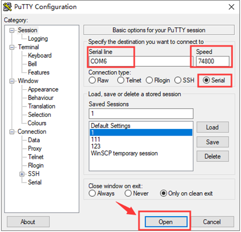
4.Insert the ESP8266 module into the ESP-01 Programmer module, putty prints the following information, and the IP is successfully read.</p><p><em>Note: Insert the ESP8266 module into the ESP-01 Programmer module after clicking “Open”, otherwise it is invalid.</em></p><div class="embedExternal embedImage display-medium float-none"> <div class="embedExternal-content"> <a class="embedImage-link" href="https://us.v-cdn.net/6031942/uploads/7DSJZCSFS64U/image.png" rel="nofollow noreferrer noopener ugc" target="_blank"> <img class="embedImage-img" src="https://us.v-cdn.net/6031942/uploads/7DSJZCSFS64U/image.png" alt="image.png" height="446" width="709" loading="lazy" data-display-size="medium" data-float="none"></img></a> </div> </div> <p><em>Remember IP name is 192.168.3.12, please.</em></p><p> 5. The computer and the home wifi are in the same segment and local area network. Connect computer to your home WiFi. </p><p>SSID : KeyesWifi_S Password: KeyesWifi.</p><p><br></p><p> 6. Plug the ESP8266 module into the ESP-01 Breakout Board. Insert the breakout board to the breadboard, connect an LED, and DC 3.3V power supply.</p><div class="embedExternal embedImage display-medium float-none"> <div class="embedExternal-content"> <a class="embedImage-link" href="https://us.v-cdn.net/6031942/uploads/AB63DY4AXDO3/image.png" rel="nofollow noreferrer noopener ugc" target="_blank"> <img class="embedImage-img" src="https://us.v-cdn.net/6031942/uploads/AB63DY4AXDO3/image.png" alt="image.png" height="499" width="709" loading="lazy" data-display-size="medium" data-float="none"></img></a> </div> </div> <p>
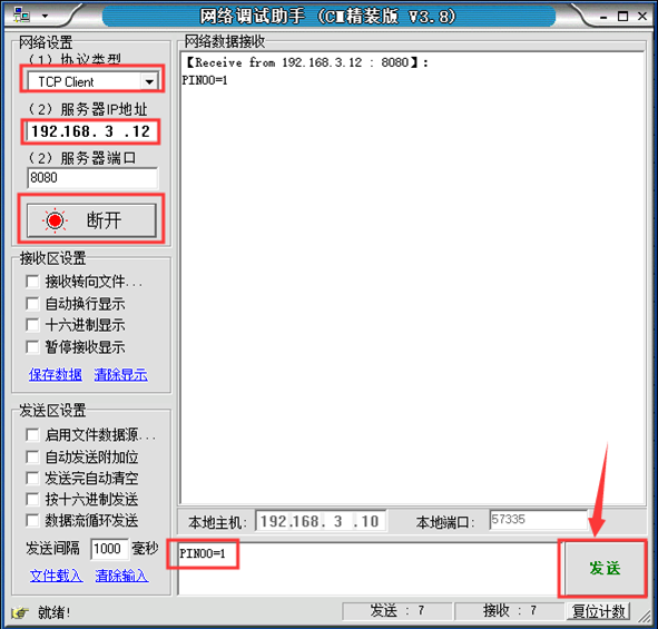
7. Open the network debugging assistant software, as shown below:</p><div class="embedExternal embedImage display-medium float-none"> <div class="embedExternal-content"> <a class="embedImage-link" href="https://us.v-cdn.net/6031942/uploads/LUINW5A9NTV4/image.png" rel="nofollow noreferrer noopener ugc" target="_blank"> <img class="embedImage-img" src="https://us.v-cdn.net/6031942/uploads/LUINW5A9NTV4/image.png" alt="image.png" height="565" width="591" loading="lazy" data-display-size="medium" data-float="none"></img></a> </div> </div> <p>8. Send PIN00 = 1 signal, the external LED lights up, as shown below:</p><div class="embedExternal embedImage display-medium float-none"> <div class="embedExternal-content"> <a class="embedImage-link" href="https://us.v-cdn.net/6031942/uploads/Z29AMVRNEL7I/image.png" rel="nofollow noreferrer noopener ugc" target="_blank"> <img class="embedImage-img" src="https://us.v-cdn.net/6031942/uploads/Z29AMVRNEL7I/image.png" alt="image.png" height="565" width="591" loading="lazy" data-display-size="medium" data-float="none"></img></a> </div> </div> <p>9. Send PIN00 = 0 signal, the external LED is off, as shown below.</p><div class="embedExternal embedImage display-medium float-none"> <div class="embedExternal-content"> <a class="embedImage-link" href="https://us.v-cdn.net/6031942/uploads/CHRKJGXSVKUH/image.png" rel="nofollow noreferrer noopener ugc" target="_blank"> <img class="embedImage-img" src="https://us.v-cdn.net/6031942/uploads/CHRKJGXSVKUH/image.png" alt="image.png" height="565" width="591" loading="lazy" data-display-size="medium" data-float="none"></img></a> </div> </div> <p>
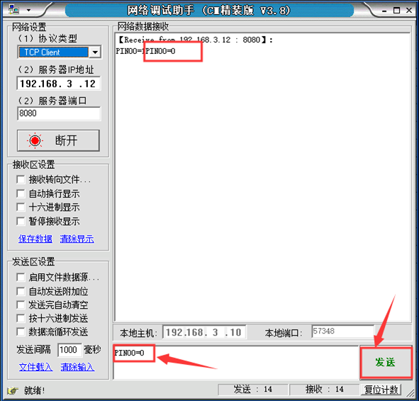
Complete the test for station mode operation.</p><p><br></p><h2 data-id="softap-mode-1">Softap Mode</h2><p>(1) When the computer and the home wifi are in the same segment and local area network, change the home WiFi name into another one to prevent the WIFIModule from automatically connecting.</p><p>(2) Connect computer to WiFi, the name is KeyesWifi_A, and the password is KeyesWifi.</p><p>(3) Connect the circuit according to the following wiring diagram: connect 3.3V power supply and wait for 20 seconds.</p><div class="embedExternal embedImage display-medium float-none"> <div class="embedExternal-content"> <a class="embedImage-link" href="https://us.v-cdn.net/6031942/uploads/WATZULH3KECV/image.png" rel="nofollow noreferrer noopener ugc" target="_blank"> <img class="embedImage-img" src="https://us.v-cdn.net/6031942/uploads/WATZULH3KECV/image.png" alt="image.png" height="499" width="709" loading="lazy" data-display-size="medium" data-float="none"></img></a> </div> </div> <p>(4) Open the network debugging assistant software, as shown below.</p><div class="embedExternal embedImage display-medium float-none"> <div class="embedExternal-content"> <a class="embedImage-link" href="https://us.v-cdn.net/6031942/uploads/1MIQVLH5ZIG0/image.png" rel="nofollow noreferrer noopener ugc" target="_blank"> <img class="embedImage-img" src="https://us.v-cdn.net/6031942/uploads/1MIQVLH5ZIG0/image.png" alt="image.png" height="565" width="591" loading="lazy" data-display-size="medium" data-float="none"></img></a> </div> </div> <p>(5) Send PIN00 = 1, the external LED lights up, as shown below</p><div class="embedExternal embedImage display-medium float-none"> <div class="embedExternal-content"> <a class="embedImage-link" href="https://us.v-cdn.net/6031942/uploads/YVD4PY9GY4MV/image.png" rel="nofollow noreferrer noopener ugc" target="_blank"> <img class="embedImage-img" src="https://us.v-cdn.net/6031942/uploads/YVD4PY9GY4MV/image.png" alt="image.png" height="565" width="591" loading="lazy" data-display-size="medium" data-float="none"></img></a> </div> </div> <p>(6) Send PIN00 = 0, the external LED is off, as shown below.</p><div class="embedExternal embedImage display-medium float-none"> <div class="embedExternal-content"> <a class="embedImage-link" href="https://us.v-cdn.net/6031942/uploads/WD399HGPGLXX/image.png" rel="nofollow noreferrer noopener ugc" target="_blank"> <img class="embedImage-img" src="https://us.v-cdn.net/6031942/uploads/WD399HGPGLXX/image.png" alt="image.png" height="565" width="591" loading="lazy" data-display-size="medium" data-float="none"></img></a> </div> </div> <p>(7) Complete the test for softap mode operation</p> </article> </main>