
Kit Introduction
This Basic Starter V2.0 upgraded kit is developed specially for those who are interested in Arduino. You will have a set of Arduino's most common and useful electronic components.
What's more, we will offer you a detailed tutorials including project introduction, connection diagram, source code and more. You may learn about Arduino from basic projects to more complex projects. This kit will help you control the physical world with sensors.

Kit List


Install Arduino IDE and Driver
Installing Arduino IDE
When we get control board, we need to download Arduino IDE and driver firstly.
You could download Arduino IDE from the official website
https//www.arduino.cc/, click the SOFTWARE on the browse bar, click “DOWNLOADS” to enter download page, as shown below

There are various versions Of IDE for Arduino, just download a version that compatible with your system, here we will show you how to download and install the windows version Arduino IDE.

There are two versions of IDE for WINDOWS system, you can choose between the Installer (.exe) and the Zip packages. We suggest you use the first one that installs directly everything you need to use the Arduino Software (IDE), including the drivers. With the Zip package you need to install the drivers manually. The Zip file is also useful if you want to create a portable installation.

You just need to click JUST DOWNLOAD.
V4.0 Development Board
We need to know V4.0 development board, as a core of this kit.

V4.0 development board is an Arduino board, which is based on ATmega328P MCU, and with a cp2102 Chip as a UART-to-USB converter.
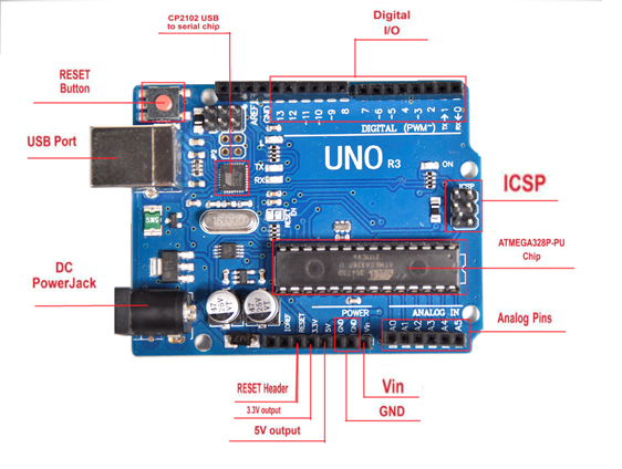
It has 14 digital input/output pins (of which 6 can be used as PWM outputs), 6 analog inputs, a 16 MHz quartz crystal, a USB connection, a power jack, 2 ICSP headers and a reset button.

It contains everything needed to support the microcontroller; simply connect it to a computer with a USB cable or power it via an external DC power jack (DC 7-12V) or via female headers Vin/ GND(DC 7-12V) to get started.

MEGA 2560 Board
Mega 2560 R3 is a microV4.0 Board or MEGA 2650 Board based on the ATMEGA2560-16AU , fully compatible with ARDUINO MEGA 2560 R3.

It has 54 digital input/output pins (of which 15 can be used as PWM outputs), 16 analog inputs, 4 UARTs (hardware serial ports), a 16 MHz crystal oscillator, a USB connection, a power jack, 1 ICSP header, and a reset button. The built-in ICSP port can burn the firmware for ATMEGA2560-16AU directly. This chip is burnt the firmware well before leaving the factory, therefore, we hardly use it. We can power on by USB wire, DC head and Vin GND pins. To facilitate wiring, a 0.5 m USB wire is provided for you.

Specialized Functions of Some Pins:
1. Serial Communication: D0 (RX0) and D1 (TX1); Serial 1: D19 (RX1) and D18 (TX1); Serial 2: D17 (RX2) and D16 (TX2); Serial 3: D15 (RX3) and D14 (TX3). Used to receive (RX) and transmit (TX) TTL serial data. Pins 0 and 1 are also connected to the corresponding pins of the CP2102 USB-to-TTL Serial chip.
2. PWM Pins (Pulse-Width Modulation): D2 to D13, and D44 to D46. Provide 8-bit PWM output with the analogWrite() function.
3. External Interrupts: D2 (interrupt 0), D3 (interrupt 1), D18 (interrupt 5), D19 (interrupt 4), D20 (interrupt 3), and D21 (interrupt 2). These pins can be configured to trigger an interrupt on a low level, a rising or falling edge, or a change in level. See the attachInterrupt() function for details.
4. SPI communication: D53 (SS), D52 (SCK), D51 (MOSI), D50 (MISO). These pins support SPI communication using theSPI library. The SPI pins are also broken out on the ICSP header, which is physically compatible with the Arduino Uno.
5. IIC communication: D20 (SDA); D21 (SCL). Support TWI communication using the Wire library.
Installing V4.0 board Driver
Let’s install the driver of V4.0 board. The USB-TTL chip on V4.0 board adopts CP2102 serial chip. The driver program of this chip is included in Arduino 1.8 version and above, which is convenient. Plug on USB port of board, the computer can recognize the hardware and automatically install the driver of CP2102.
If install unsuccessfully, or you intend to install manually, open the device manager of computer. Right click Computer----- Properties----- Device Manager

There is a yellow exclamation mark on the page, which implies installing unsuccessfully. Then we double click the hardware and update the driver.

Click “OK” to enter the following page, click “browse my computer for updated driver software”, find out the installed or downloaded ARDUINO software. As shown below

There is a DRIVERS folder in Arduino software installed package open driver folder and you can see the driver of CP210X series chips.
We click “Browse”, then find out the driver folder, or you could enter “driver” to search in rectangular box, then click “next”, the driver will be installed successfully. (I place Arduino software folder on the desktop, you could follow my way)

Open device manager, we will find the yellow exclamation mark disappear. The driver of CP2102 is installed successfully.


The installation method of MEGA 2560 board and V4.0 board is same
(5)Arduino IDE Setting
Click the Arduino icon, open Arduino IDE.

To avoid the errors when uploading the program to the board, you need to select the correct V4.0 Board or MEGA 2650 Board that matches the board connected to your computer.
Then come back to the Arduino software, you should click Tools→Board, select the board. (as shown below)

Then select the correct COM port (you can see the corresponding COM port after the driver is successfully installed)

Before uploading the program to the board, let’s demonstrate the function of each symbol in the Arduino IDE toolbar.

A- Used to verify whether there is any compiling mistakes or not.
B- Used to upload the sketch to yourV4.0 Board or MEGA 2650 Board*1 .
C- Used to create shortcut window of a new sketch.
D- Used to directly open an example sketch.
E- Used to save the sketch.
F- Used to send the serial data received from board to the serial monitor.
Start First Program
Open the file to select Example, choose BLINK from BASIC, as shown below


Set board and COM port, the corresponding board and COM port are shown on the lower right of IDE.

Click the Check icon to start compiling the program, check errors.

Click the Arron icon to upload the program, upload successfully.

Upload the program successfully, the onboard LED lights on for 1s, lights off for 1s. Congratulation, you finish the first program.
If it is MEGA 2560 board, please select Arduino MEGA or MEGA 2560 board
How to Add a Library?
What are Libraries ?
Libraries are a collection of code that makes it easy for you to connect to a sensor,display, module, etc.
For example, the built-in LiquidCrystal library helps talk to LCD displays. There are hundreds of additional libraries available on the Internet for download.
The built-in libraries and some of these additional libraries are listed in the reference.
How to Install a Library ?
Here we will introduce the most simple way for you to add libraries .
Step 1After downloading well the Arduino IDE, you can right-click the icon of Arduino IDE.
Find the option "Open file location" shown as below

Step 2 Enter it to find out libraries folder, this folder is the library file of Arduino.

Step 3 Next to find out the “libraries” folder of this kit

You just need to replicate and paste above libraries into the libraries folder of Arduino IDE.
Then the libraries of this kit are installed successfully, as shown below
Note the Arduino software download and the driver installation of Mega 2560 R3 board is similar to arduino V4.0 board.
Project Details
Project 1: Hello World
1)Introduction
As for starters, we will begin with something simple. In this project, you only need an Arduino and a USB cable to start the "Hello World!" experiment.
This is a communication test of your Arduino and PC, also a primer project for you to have your first try of the Arduino world!
2)Hardware required
1.V4.0 Board or MEGA 2650 Board x1
2. USB cable x1
3)Sample program
After installing driver for Arduino, let's open Arduino software and compile code that enables Arduino to print "Hello World!" under your instruction.
Of course, you can compile code for Arduino to continuously echo "Hello World!" without instruction.
A simple If () statement will do the instruction trick. With the onboard LED connected to pin 13, we can instruct the LED to blink first when Arduino gets an instruction and then prints "Hello World!”.
//////////////////////////////////////////////////////////
int val;//define variable val
int ledpin=13;// define digital interface 13
void setup()
{
Serial.begin(9600);// set the baud rate at 9600 to match the software set up. When connected to a specific device, (e.g. bluetooth), the baud rate needs to be the same with it.
pinMode(ledpin,OUTPUT);// initialize digital pin 13 as output. When using I/O ports on an Arduino, this kind of set up is always needed.
}
void loop()
{
val=Serial.read();// read the instruction or character from PC to Arduino, and assign them to Val.
if(val=='R')// determine if the instruction or character received is “R”.
{ // if it’s “R”,
digitalWrite(ledpin,HIGH);// set the LED on digital pin 13 on.
delay(500);
digitalWrite(ledpin,LOW);// set the LED on digital pin 13 off. delay(500);
Serial.println("Hello World!");// display“Hello World!”string.
}
}
////////////////////////////////////////////////////////////////
4)Result Show


Done compiling and uploading the code, click to open serial port monitor and set the baud rate to 9600.
Enter an “R” and click Send.
LED 13 will blink once, and your PC will receive information from Arduino: Hello World.

Now, the experiment is complete, so easy!
Note: if upload failed ?
Check whether you select the correct Board and Port in Tools.

Project 2: LED blinking
1)Introduction
Blinking LED experiment is quite simple. In the "Hello World!" program, we have come across LED. This time, we are going to connect an LED to one of the digital pins rather than using the built-in LED13 of V4.0 Board or MEGA 2650 Board. Except an Arduino and an USB cable, we will need extra parts below.
2)Hardware required
1. V4.0 Board or MEGA 2650 Board *1
2. Red M5 LED*1
3. 220Ω resistor*1
4. Breadboard*1
5. USB cable *1
6. Jumper wire* 2


We follow the connection diagram below to connect the components.
Here we use digital pin 10. We connect LED to a 220ohm resistor to avoid high current damaging the LED.
3)Connection for V4.0:

Connection for 2560 R3:

4)Sample program
//////////////////////////////////////////////////////////
int ledPin = 10; // define digital pin 10.
void setup()
{
pinMode(ledPin, OUTPUT);// define pin with LED connected as output.
}
void loop()
{
digitalWrite(ledPin, HIGH); // set the LED on.
delay(1000); // wait for a second.
digitalWrite(ledPin, LOW); // set the LED off.
delay(1000); // wait for a second
}
//////////////////////////////////////////////////////////
5)Test Result
After downloading this program, in the experiment, you will see the LED connected to pin 10 turning on and off, with an interval approximately one second.
The blinking LED experiment is now completed. Thank you!
Project 3: PWM
1)Introduction
PWM, short for Pulse Width Modulation, is a technique used to encode analog signal level into digital ones.
A computer cannot output analog voltage but only digital voltage values such as 0V or 5V. So we use a high resolution counter to encode a specific analog signal level by modulating the duty cycle of PMW.
The PWM signal is also digitalized because in any given moment, fully on DC power supply is either 5V (ON), or 0V (OFF). The voltage or current is fed to the analog load (the device that uses the power) by repeated pulse sequence being ON or OFF. Being on, the current is fed to the load; being off, it's not.
With adequate bandwidth, any analog value can be encoded using PWM. The output voltage value is calculated via the on and off time.
Output voltage = (turn on time/pulse time) * maximum voltage value

PWM has many applications: lamp brightness regulating, motor speed regulating, sound making, etc.
The following are the three basic parameters of PMW:

1. The amplitude of pulse width (minimum / maximum)
2. The pulse period (The reciprocal of pulse frequency in 1 second)
3. The voltage level (such as 0V-5V )
There are 6 PMW pins onV4.0 Board or MEGA 2650 Board*1 , namely digital pin 3, 5, 6, 9, 10, and 11.
In previous experiments, we have done "button-controlled LED", using digital signal to control digital pin.
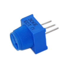
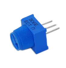
This time, we will use a potentiometer to control the brightness of LED.
2)Hardware required
1. V4.0 Board or MEGA 2650 Board *1
2. Potentiometer *1
3. Red M5 LED *1
4. 220Ω resistor *1
5. Breadboard *1
6. USB cable *1
7. Breadboard jumper wire * 6
The input of potentiometer is analog, so we connect it to analog port, and LED to PWM port. Different PWM signal can regulate the brightness of the LED.
3)Connection for V4.0:

Connection for 2560 R3:

4)Sample program
In the program compiling process, we will use the analogWrite (PWM interface, analog value) function.
In this experiment, we will read the analog value of the potentiometer and assign the value to PWM port, so there will be corresponding change to the brightness of the LED.
One final part will be displaying the analog value on the monitor window.
You can consider this as the "analog value reading" project adding the PWM analog value assigning part.
Below is a sample program for your reference.
//////////////////////////////////////////////////////////
int potpin=0;// initialize analog pin 0
int ledpin=11;//initialize digital pin 11(PWM output)
int val=0;// Temporarily store variables' value from the sensor
void setup()
{
pinMode(ledpin,OUTPUT);// define digital pin 11 as “output”
Serial.begin(9600);// set baud rate at 9600
// attention: for analog ports, they are automatically set up as “input”
}
void loop()
{
val=analogRead(potpin);// read the analog value from the sensor and assign it to val
Serial.println(val);// display value of val
analogWrite(ledpin,val/4);// turn on LED and set up brightness(maximum output of PWM is 255)
delay(10);// wait for 0.01 second
}
//////////////////////////////////////////////////////////

5)Test Result
After uploading the program to the board, rotate the potentiometer knob, you can see the changes of displaying value, and also obvious change of LED brightness.
Project 4: Traffic light
1)Introduction
In the previous program, we have done the LED blinking experiment with one LED. Now, it’s time to up the stakes and do a bit more complicated experiment-traffic lights. Actually, these two experiments are similar. While in this traffic lights experiment, we use 3 LEDs with different colors rather than 1 LED.
2)Hardware required
1.V4.0 Board or MEGA 2650 Board*1
2. USB cable *1
3. Red M5 LED*1
4. Yellow M5 LED*1
5. Green M5 LED*1
6. 220Ω resistor *3
7. Breadboard*1
8. Breadboard jumper wires* several
3)Connection for V4.0:

Connection for 2560 R3:

4)Sample program
Since it is a simulation of traffic lights, the blinking time of each LED should be the same with those in traffic lights system.
In this program, we use Arduino delay () function to control delay time, which is much simpler than C language.
//////////////////////////////////////////////////////////
int redled =10; // initialize digital pin 8.
int yellowled =7; // initialize digital pin 7.
int greenled =4; // initialize digital pin 4.
void setup()
{
pinMode(redled, OUTPUT);// set the pin with red LED as “output”
pinMode(yellowled, OUTPUT); // set the pin with yellow LED as “output”
pinMode(greenled, OUTPUT); // set the pin with green LED as “output”
}
void loop()
{
digitalWrite(greenled, HIGH);//// turn on green LED
delay(5000);// wait 5 seconds
digitalWrite(greenled, LOW); // turn off green LED
for(int i=0;i<3;i++)// blinks for 3 times
{
delay(500);// wait 0.5 second
digitalWrite(yellowled, HIGH);// turn on yellow LED
delay(500);// wait 0.5 second
digitalWrite(yellowled, LOW);// turn off yellow LED
}
delay(500);// wait 0.5 second
digitalWrite(redled, HIGH);// turn on red LED
delay(5000);// wait 5 seconds
digitalWrite(redled, LOW);// turn off red LED
}
//////////////////////////////////////////////////////////
5)Test Result
When the uploading process is completed, you can see your own traffic light design.
The green light will be on for 5 seconds, and then off., followed by the yellow light blinking for 3 times, and then the red light on for 5 seconds, forming a cycle. Cycle then repeats.
Experiment is now completed, thank you.
Note: this circuit design is very similar with the following LED chasing effect.
Project 5: LED chasing effect

1)Introduction
We often see billboards composed of colorful LEDs. They are constantly changing to form various light effects. In this experiment, we compile a program to simulate LED chasing effect.
2)Hardware required
1. Led *6
2. V4.0 Board or MEGA 2650 Board *1
3. 220Ω resistor *6
4. Breadboard *1
5. USB cable*1
6. Breadboard wire *13
3)Connection for V4.0:

Connection for 2560 R3:

4)Sample program
//////////////////////////////////////////////////////////
int BASE = 2 ; // the I/O pin for the first LED
int NUM = 6; // number of LEDs
void setup()
{
for (int i = BASE; i < BASE + NUM; i ++)
{
pinMode(i, OUTPUT); // set I/O pins as output
}
}
void loop()
{
for (int i = BASE; i < BASE + NUM; i ++)
{
digitalWrite(i, LOW); // set I/O pins as “low”, turn off LEDs one by one.
delay(200); // delay
}
for (int i = BASE; i < BASE + NUM; i ++)
{
digitalWrite(i, HIGH); // set I/O pins as “high”, turn on LEDs one by one
delay(200); // delay
}
}
//////////////////////////////////////////////////////////
5)Result
You can see the LEDs blink by sequence.
Project 6: Button-controlled LED
1)Introduction
I/O port means interface for INPUT and OUTPUT. Up until now, we have only used the OUTPUT function.
In this experiment, we will try to use the input function, which is to read the output value of device. We use 1 button and 1 LED using both input and output to give you a better understanding of the I/O function.
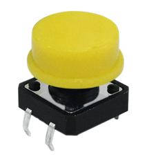
Button switches, familiar to most of us, are a switch value (digital value) component. When it's pressed, the circuit is in closed (conducting) state.
2)Hardware required
1. V4.0 Board or MEGA 2650 Board *1
2. Button switch *1
3. Red M5 LED *1
4. 220Ω resistor *1
5. 10KΩ resistor *1
6. Breadboard *1
7. USB cable *1
8. Breadboard jumper wire * 6
Connection for V4.0:

Connection for 2560 R3:

3)Sample program
Now, let's begin the compiling. When the button is pressed, the LED will be on. After the previous study, the coding should be easy for you.
In this program, we add a statement of judgment. Here, we use an if () statement.
Arduino IDE is based on C language, so statements of C language such as while, switch can certainly be used for Arduino program.
When we press the button, pin 7 will output high level. We can program pin 11 to output high level and turn on the LED.
When pin 7 outputs low level, pin 11 also outputs low level and the LED remains off.
//////////////////////////////////////////////////////////
int ledpin=11;// initialize pin 11
int inpin=7;// initialize pin 7
int val;// define val
void setup()
{
pinMode(ledpin,OUTPUT);// set LED pin as “output”
pinMode(inpin,INPUT);// set button pin as “input”
}
void loop()
{
val=digitalRead(inpin);// read the level value of pin 7 and assign if to val
if(val==LOW)// check if the button is pressed, if yes, turn on the LED
{ digitalWrite(ledpin,LOW);}
else
{ digitalWrite(ledpin,HIGH);}
}
//////////////////////////////////////////////////////////
(4)Result
When the button is pressed, LED is on; otherwise, LED remains off. Congrats! the button controlled LED experiment is completed.
The simple principle of this experiment is widely used in a variety of circuit and electric appliances. You can easily come across it in your every day life. One typical example is when you press a certain key of your phone, the backlight will be on.
Project 7: Active buzzer

1)Introduction
Active buzzer is a sound making element, widely used on computer, printer, alarm, electronic toy, telephone, timer, etc. It has an inner vibration source. Simply connect it with 5V power supply, it can buzz continuously.
2)Hardware required
1. Buzzer *1
2. V4.0 Board or MEGA 2650 Board *1
3. Breadboard *1
4. USB cable *1
5. Breadboard jumper wires * 2
3)Connection for V4.0:

Connection for 2560 R3:

When connecting the circuit, pay attention to the positive and negative poles of the buzzer. In the photo, you can see there are red and black lines. When the circuit is finished, you can begin programming.
4)Sample program
Program is simple. You control the buzzer by outputting high/low level.
//////////////////////////////////////////////////////////
int buzzer=8;// initialize digital IO pin that controls the buzzer
void setup()
{
pinMode(buzzer,OUTPUT);// set pin mode as “output”
}
void loop()
{
digitalWrite(buzzer, HIGH); // produce sound
}
//////////////////////////////////////////////////////////
5)Result
After downloading the program, the buzzer experiment is completed.
You can hear the buzzer is ringing.
Project 8: Passive buzzer

1)Introduction
We can use Arduino to make many interactive works of which the most commonly used is acoustic-optic display.
All the previous experiment has something to do with LED. However, the circuit in this experiment can produce sound. Normally, the experiment is done with a buzzer or a speaker while buzzer is more simpler and easier to use.
The buzzer we introduced here is a passive buzzer. It cannot be actuated by itself, but by external pulse frequencies. Different frequencies produce different sounds. We can use Arduino to code the melody of a song, which is quite fun and simple.

2)Hardware required
l Passive buzzer*1
l V4.0 Board or MEGA 2650 Board *1
l Breadboard*1
l USB cable *1
l Breadboard jumper wire * 2
3)Connection for V4.0:
Here we connect the passive buzzer to digital pin 8.

Connection for 2560 R3:

4)Sample program
//////////////////////////////////////////////////////////
int buzzer=8;// select digital IO pin for the buzzer
void setup()
{
pinMode(buzzer,OUTPUT);// set digital IO pin pattern, OUTPUT to be output
}
void loop()
{ unsigned char i,j;//define variable
while(1)
{ for(i=0;i<80;i++)// output a frequency sound
{ digitalWrite(buzzer,HIGH);// sound
delay(1);//delay1ms
digitalWrite(buzzer,LOW);//not sound
delay(1);//ms delay
}
for(i=0;i<100;i++)// output a frequency sound
{
digitalWrite(buzzer,HIGH);// sound
digitalWrite(buzzer,LOW);//not sound
delay(2);//2ms delay
}
}
}
//////////////////////////////////////////////////////////
5)Result
After downloading the program, buzzer experiment is finished. You can hear the buzzer beep.
Project 9: RGB LED

1)Introduction
Tricolor principle to display various colors;
PWM controlling ports to display full color;
Can be driven directly by Arduino PWM interfaces.

2)Hardware required
1. V4.0 Board or MEGA 2650 Board × 1
2. Full-color RGB LED × 1
3. Resistor x 3
4. Breadboard x 1
5. USB cable x 1
6. Jumper wire x 5
3)Connection for V4.0:

Connection for 2560 R3:

4)Sample program
//////////////////////////////////////////////////////////
int redpin = 11; //select the pin for the red LED
int bluepin =10; // select the pin for the blue LED
int greenpin =9;// select the pin for the green LED
int val;
void setup() {
pinMode(redpin, OUTPUT);
pinMode(bluepin, OUTPUT);
pinMode(greenpin, OUTPUT);
Serial.begin(9600);
}
void loop()
{
for(val=255; val>0; val--)
{
analogWrite(11, val);
analogWrite(10, 255-val);
analogWrite(9, 128-val);
delay(1);
}
for(val=0; val<255; val++)
{
analogWrite(11, val);
analogWrite(10, 255-val);
analogWrite(9, 128-val);
delay(1);
}
Serial.println(val, DEC);
}
//////////////////////////////////////////////////////////
5)Result
Directly copy the above code into arduino IDE, and click upload, wait for a few seconds, you can see a full-color RGB LED flash.
Project 10: Photo Resistor

1)Introduction
After completing all the previous experiments, we acquired some basic understanding and knowledge about Arduino application. We have learned digital input and output, analog input and PWM. Now, we can begin the learning of sensors applications.
Photo-Resistor (Photovaristor) is a resistor whose resistance varies according to different incident light strength.
It's made based on the photoelectric effect of semiconductor. If the incident light is intense, its resistance reduces; if the incident light is weak, the resistance increases.
Photovaristor is commonly applied in the measurement of light, light control and photovoltaic conversion (convert the change of light into the change of electricity).
Photo resistor is also being widely applied to various light control circuits, such as light control and adjustment, optical switches, etc.
We will start with a relatively simple experiment regarding photovaristor application.
Photovaristor is an element that changes its resistance as light strength changes. So we will need to read the analog values. We can refer to the PWM experiment, replacing the potentiometer with photovaristor. When there is change in light strength, there will be corresponding change on the LED.
2)Hardware required
1. Photo-resistor sensor *1
2. V4.0 Board or MEGA 2650 Board*1
3. Red M5 LED *1
4. 10KΩ resistor *1
5. 220Ω resistor *1
6. Breadboard *1
7. USB cable *1
8. Breadboard jumper wire * 5
3)Connection for V4.0:

Connection for 2560 R3:

4)Sample program
After the connection, let's begin the program compiling. The program is similar to the one of PWM. For change detail, please refer to the sample program below.
//////////////////////////////////////////////////////////
int potpin=0;// initialize analog pin 0, connected with photovaristor
int ledpin=11;// initialize digital pin 11, output regulating the brightness of LED
int val=0;// initialize variable val
void setup()
{
pinMode(ledpin,OUTPUT);// set digital pin 11 as “output”
Serial.begin(9600);// set baud rate at “9600”
}
void loop()
{
val=analogRead(potpin);// read the analog value of the sensor and assign it to val
Serial.println(val);// display the value of val
analogWrite(ledpin,val);// turn on the LED and set up brightness(maximum output value 255)
delay(10);// wait for 0.01
}
//////////////////////////////////////////////////////////
5)Result
After downloading the program, you can change the light strength around the photovaristor and see corresponding brightness change of the LED.
Photovaristors has various applications in our everyday life. You can make other interesting interactive projects base on this one.
Project 11: Flame sensor
1)Introduction
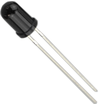
Flame sensor (Infrared receiving triode) is specially used on robots to find the fire source. This sensor is of high sensitivity to flame. Below is a photo of it.
2)Working principle:
Flame sensor is made based on the principle that infrared ray is highly sensitive to flame. It has a specially designed infrared receiving tube to detect fire, and then convert the flame brightness into fluctuating level signal. The signals are then input into the central processor and be dealt with accordingly.
3)Sensor connection
The shorter lead of the receiving triode is for negative, the other one for positive. Connect negative to 5V pin, positive to resistor; connect the other end of the resistor to GND, connect one end of a jumper wire to a clip which is electrically connected to sensor positive, the other end to analog pin. As shown below:

4)Hardware required
1. Flame sensor *1
2. V4.0 Board or MEGA 2650 Board*1
3. Buzzer *1
4. 10K resistor *1
5. USB cable *1
6. Breadboard jumper wire * 6
5)Connection for V4.0:
Connecting buzzer:
Connect the buzzer to digital pin 8.
Connecting flame sensor:
Connect the flame sensor to analog pin 0.

Connection for 2560 R3:

Experiment principle
When it's approaching a fire, the voltage value read from the analog port differs.
If you use a multimeter, you can know when there is no fire approaching, the voltage it reads is around 0.3V; when there is fire approaching, the voltage it reads is around 1.0V. The nearer the fire, the higher the voltage is.
So in the beginning of the program, you can initialize voltage value i (no fire value); Then, continuously read the analog voltage value j and obtain difference value k=j-i; compare k with 0.6V (123 in binary) to determine whether there is a fire approaching or not; if yes, the buzzer will buzz.
6)Sample program
////////////////////////////////////////////////////////////////
int flame=0;// select analog pin 0 for the sensor
int Beep=9;// select digital pin 9 for the buzzer
int val=0;// initialize variable
void setup()
{
pinMode(Beep,OUTPUT);// set LED pin as “output”
pinMode(flame,INPUT);// set buzzer pin as “input”
Serial.begin(9600);// set baud rate at “9600”
}
void loop()
{
val=analogRead(flame);// read the analog value of the sensor
Serial.println(val);// output and display the analog value
if(val>=600)// when the analog value is larger than 600, the buzzer will buzz
{
digitalWrite(Beep,HIGH);
}else
{
digitalWrite(Beep,LOW);
}
delay(500);
}
////////////////////////////////////////////////////////////////
7)Result
This program can simulate an alarm when there is a fire.
Everything is normal when there is no fire; but when there is a fire, the alarm will be set off immediately.
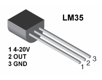
Project 12: LM35 temperature sensor

1)Introduction
LM35 is a common and easy-to-use temperature sensor. It does not require other hardware. You just need an analog port to make it work. The difficulty lies in compiling the code to convert the analog value it reads into Celsius temperature.
2)Hardware required
1. LM35*1
2. V4.0 or MEGA 2650 Board*1
3. Breadboard*1
4. USB cable *1
5. Breadboard jumper wire *5
3)Connection for V4.0:

Connection for 2560 R3:

4)Sample program
//////////////////////////////////////////////////////////
int potPin = 0; // initialize analog pin 0 for LM35 temperature sensor
void setup()
{
Serial.begin(9600);// set baud rate at”9600”
}
void loop()
{
int val;// define variable
int dat;// define variable
val=analogRead(0);// read the analog value of the sensor and assign it to val
dat=(125*val)>>8;// temperature calculation formula
Serial.print("Tep:");// output and display characters beginning with Tep
Serial.print(dat);// output and display value of dat
Serial.println("C");// display “C” characters
delay(500);// wait for 0.5 second
}
//////////////////////////////////////////////////////////
5)Result
After downloading the program, you can open the monitoring window to see current temperature.

Project 13: Ball tilt switch

1)Introduction
This lesson let’s use a ball tilt switch to control the ON and OFF of LED
2)Hardware required
1. Ball switch*1
2. V4.0 Board or MEGA 2650 Board*1
3. Led*1
4. 220Ω resistor*1
5. 10KΩ resistor*1
6. USB cable *1
7. Breadboard jumper wire *5
3)Connection for V4.0:
Connect the ball tilt switch, LED and resistors to control board. Connect the LED to digital pin 8, ball switch to analog pin 5.

Connection for 2560 R3:

Experiment principle
When one end of the switch is below horizontal position, the switch is on. The voltage of the analog port is about 5V (1023 in binary). The LED will be on.
When the other end of the switch is below horizontal position, the switch is off. The voltage of the analog port is about 0V (0 in binary). The LED will be off.
In the program, we determine whether the switch is on or off according to the voltage value of the analog port, whether it's above 2.5V (512 in binary) or not.
4)Sample program
//////////////////////////////////////////////////////////
void setup()
{
pinMode(8,OUTPUT);// set digital pin 8 as “output”
}
void loop()
{
int i;// define variable i
while(1)
{
i=analogRead(5);// read the voltage value of analog pin 5
if(i>512)// if larger that 512(2.5V)
{
digitalWrite(8,LOW);// turn on LED
}
else// otherwise
{
digitalWrite(8,HIGH);// turn off LED
}
}
}
//////////////////////////////////////////////////////////
5)Test Result
Hold the breadboard with your hand. Tilt it to a certain angle, so the tiny ball inside tilt switch is conducted, the LED will be on.
If there is no tilt, the LED will be off.
The principle of this experiment can also be applied to relay control.
Experiment completed.
Thank you!
Project 14: Analog value reading
1)Introduction
In this experiment, we will begin the learning of analog I/O interfaces.
On an Arduino, there are 6 analog interfaces numbered from 0 to 5. These 6 interfaces can also be used as digital ones numbered as 14-19.
After a brief introduction, let's begin our project. Potentiometer used here is a typical output component of analog value that is familiar to us.
2)Hardware required
- V4.0 Board or MEGA 2650 Board*1
- Potentiometer *1
- V4.0 Board or MEGA 2650 Board *1
- Breadboard*1
- USB cable *1
- Breadboard jumper wire * 3
3)Circuit connection
In this experiment, we will convert the resistance value of the potentiometer to analog ones, and display the analog value on the screen.
This is an application we need to master well for our future experiments.
Connection circuit as below:
Connection for V4.0:

The analog interface we use here is interface 0.
Connection for 2560 R3:

4)Sample program
The program compiling is simple. An analogRead () Statement can read the value of the interface. The A/D acquisition of Arduino 328 is in 10 bits, so the value it reads is among 0 to 1023.
One difficulty in this project is to display the value on the screen, which is actually easy to learn.
First, we need to set the baud rate in voidsetup (). Displaying the value is a communication between Arduino and PC, so the baud rate of the Arduino should match the one in the PC's software setup. Otherwise, the display will be messy codes or no display at all.
In the lower right corner of the Arduino software monitor window, there is a button for baud rate set up. The setup here needs to match the one in the program.
The statement in the program is Serial.begin(); enclosed is the baud rate value, followed by statement for displaying. You can either use Serial.print() or Serial.println() statement.
Refer to the code below:
//////////////////////////////////////////////////////////
int potpin=0;// initialize analog pin 0
int ledpin=13;// initialize digital pin 13
int val=0;// define val, assign initial value 0
void setup()
{
pinMode(ledpin,OUTPUT);// set digital pin as “output”
Serial.begin(9600);// set baud rate at 9600
}
void loop()
{
digitalWrite(ledpin,HIGH);// turn on the LED on pin 13
delay(50);// wait for 0.05 second
digitalWrite(ledpin,LOW);// turn off the LED on pin 13
delay(50);// wait for 0.05 second
val=analogRead(potpin);// read the analog value of analog pin 0, and assign it to val
Serial.println(val);// display val’s value
}
//////////////////////////////////////////////////////////
5)Result
The sample program uses the built-in LED connected to pin 13. Each time the device reads a value, the LED blinks once. Below is the analog value it reads.

When you rotate the potentiometer knob, you can see the displayed value change. The reading of analog value is a very common function since most sensors output analog value. After calculation, we can have the corresponding value we need.
The experiment is now complete. Thank you.
Project 15: 74HC595

1)Introduction
To put it simply, 74HC595 is a combination of 8-digit shifting register, memorizer and equipped with tri-state output. Here, we use it to control 8 LEDs.
You may wonder why use a 74HC595 to control LED? Well, think about how many I/O it takes for an Arduino to control 8 LEDs? Yes, 8.
For an Arduino, it has only 20 I/O including analog ports. So, to save port resources, we use 74HC595 to reduce the number of ports it needs. Using 74HC595 enables us to use 3 digital I/O port to control 8 LEDs!
The 74HC595 devices contain an 8-bit serial-in, parallel-out shift register that feeds an 8-bit D-type storage register. The storage register has parallel 3-state outputs. Separate clocks are provided for both the shift and storage register.
The shift register has a direct overriding clear (SRCLR) input, serial (SER) input, and serial outputs for cascading. When the output-enable (OE) input is high, the outputs are in the high-impedance state. Both the shift register clock (SRCLK) and storage register clock (RCLK) are positive-edge triggered. If both clocks are connected together, the shift register always is one clock pulse ahead of the storage register.
2)Hardware required
- 74HC595 chip*1
- V4.0 Board or MEGA 2650 Board *1
- Red M5 LED*4
- Green M5 LED*4
- 220Ω resistor*8
- Breadboard*1
- USB cable *1
- Breadboard jumper wires*several
3)Circuit Connection
Note: for pin 13 OE port of 74HC595, it needs to connect to GND.
Connection for V4.0:

Connection for 2560 R3:

The circuit may seem complicated, but once you give it a good look, you will find it easy!
4)Sample program
//////////////////////////////////////////////////////////
int data = 2;// set pin 14 of 74HC595as data input pin SI
int clock = 5;// set pin 11 of 74hc595 as clock pin SCK
int latch = 4;// set pin 12 of 74hc595 as output latch RCK
int ledState = 0;
const int ON = HIGH;
const int OFF = LOW;
void setup()
{
pinMode(data, OUTPUT);
pinMode(clock, OUTPUT);
pinMode(latch, OUTPUT);
}
void loop()
{
for(int i = 0; i < 256; i++)
{
updateLEDs(i);
delay(500);
}
}
void updateLEDs(int value)
{
digitalWrite(latch, LOW);//
shiftOut(data, clock, MSBFIRST, ~value);// serial data “output”, high level first
digitalWrite(latch, HIGH);// latch
}
//////////////////////////////////////////////////////////
5)Result
After downloading the program, you can see 8 LEDs displaying 8-bit binary number.
Project 16: 1-digit LED display
1)Introduction
LED segment displays are common for displaying numerical information.
They are widely applied on displays of electromagnetic oven, full automatic washing machine, water temperature display, electronic clock etc.
So it is necessary that we learn how it works.

LED segment display is a semiconductor light-emitting device. Its basic unit is a light-emitting diode (LED).
LED segment display can be divided into 7-segment display and 8-segment display according to the number of segments.
8-segment display has one more LED unit (for decimal point display) than 7-segment one.
In this experiment, we use a 8-segment display. According to the wiring method of LED units, LED segment displays can be divided into display with common anode and display with common cathode.
Common anode display refers to the one that combine all the anodes of LED units into one common anode (COM).
For the common anode display, connect the common anode (COM) to +5V. When the cathode level of a certain segment is low, the segment is on; when the cathode level of a certain segment is high, the segment is off.
For the common cathode display, connect the common cathode (COM) to GND. When the anode level of a certain segment is high, the segment is on; when the anode level of a certain segment is low, the segment is off.

Each segment of the display consists of an LED. So when you use it, you also need use a current-limiting resistor. Otherwise, LED will be burnt out.
In this experiment, we use a common cathode display. As we mentioned above, for common cathode display, connect the common cathode (COM) to GND.
When the anode level of a certain segment is high, the segment is on; when the anode level of a certain segment is low, the segment is off.
2)Hardware required
- 1-digit 8-segment display *1
- 220Ω resistor *8
- Breadboard *1
- V4.0 Board or MEGA 2650 Board *1
- USB cable *1
- Breadboard jumper wire * 12
3)Circuit Connection
Connection for V4.0:

Connection for 2560 R3:

4)Sample program
There are seven segments for numerical display, one for decimal point display. Corresponding segments will be turned on when displaying certain numbers.
For example, when displaying number 1, b and c segments will be turned on.
We compile a subprogram for each number, and compile the main program to display one number every 2 seconds, cycling display number 0 ~ 9.
The displaying time for each number is subject to the delay time, the longer the delay time, the longer the displaying time.
Refer to the sample code below:
//////////////////////////////////////////////////////////
// set the IO pin for each segment
int a=7;// set digital pin 7 for segment a
int b=6;// set digital pin 6 for segment b
int c=5;// set digital pin 5 for segment c
int d=10;// set digital pin 10 for segment d
int e=11;// set digital pin 11 for segment e
int f=8;// set digital pin 8 for segment f
int g=9;// set digital pin 9 for segment g
int dp=4;// set digital pin 4 for segment dp
void digital_0(void) // display number 5
{
unsigned char j;
digitalWrite(a,HIGH);
digitalWrite(b,HIGH);
digitalWrite(c,HIGH);
digitalWrite(d,HIGH);
digitalWrite(e,HIGH);
digitalWrite(f,HIGH);
digitalWrite(g,LOW);
digitalWrite(dp,LOW);
}
void digital_1(void) // display number 1
{
unsigned char j;
digitalWrite(c,HIGH);// set level as “high” for pin 5, turn on segment c
digitalWrite(b,HIGH);// turn on segment b
for(j=7;j<=11;j++)// turn off other segments
digitalWrite(j,LOW);
digitalWrite(dp,LOW);// turn off segment dp
}
void digital_2(void) // display number 2
{
unsigned char j;
digitalWrite(b,HIGH);
digitalWrite(a,HIGH);
for(j=9;j<=11;j++)
digitalWrite(j,HIGH);
digitalWrite(dp,LOW);
digitalWrite(c,LOW);
digitalWrite(f,LOW);
}
void digital_3(void) // display number 3
{
digitalWrite(g,HIGH);
digitalWrite(a,HIGH);
digitalWrite(b,HIGH);
digitalWrite(c,HIGH);
digitalWrite(d,HIGH);
digitalWrite(dp,LOW);
digitalWrite(f,LOW);
digitalWrite(e,LOW);
}
void digital_4(void) // display number 4
{
digitalWrite(c,HIGH);
digitalWrite(b,HIGH);
digitalWrite(f,HIGH);
digitalWrite(g,HIGH);
digitalWrite(dp,LOW);
digitalWrite(a,LOW);
digitalWrite(e,LOW);
digitalWrite(d,LOW);
}
void digital_5(void) // display number 5
{
unsigned char j;
digitalWrite(a,HIGH);
digitalWrite(b, LOW);
digitalWrite(c,HIGH);
digitalWrite(d,HIGH);
digitalWrite(e, LOW);
digitalWrite(f,HIGH);
digitalWrite(g,HIGH);
digitalWrite(dp,LOW);
}
void digital_6(void) // display number 6
{
unsigned char j;
for(j=7;j<=11;j++)
digitalWrite(j,HIGH);
digitalWrite(c,HIGH);
digitalWrite(dp,LOW);
digitalWrite(b,LOW);
}
void digital_7(void) // display number 7
{
unsigned char j;
for(j=5;j<=7;j++)
digitalWrite(j,HIGH);
digitalWrite(dp,LOW);
for(j=8;j<=11;j++)
digitalWrite(j,LOW);
}
void digital_8(void) // display number 8
{
unsigned char j;
for(j=5;j<=11;j++)
digitalWrite(j,HIGH);
digitalWrite(dp,LOW);
}
void digital_9(void) // display number 5
{
unsigned char j;
digitalWrite(a,HIGH);
digitalWrite(b,HIGH);
digitalWrite(c,HIGH);
digitalWrite(d,HIGH);
digitalWrite(e, LOW);
digitalWrite(f,HIGH);
digitalWrite(g,HIGH);
digitalWrite(dp,LOW);
}
void setup()
{
int i;// set variable
for(i=4;i<=11;i++)
pinMode(i,OUTPUT);// set pin 4-11as “output”
}
void loop()
{
while(1)
{
digital_0();// display number 0
delay(1000);// wait for 1s
digital_1();// display number 1
delay(1000);// wait for 1s
digital_2();// display number 2
delay(1000); // wait for 1s
digital_3();// display number 3
delay(1000); // wait for 1s
digital_4();// display number 4
delay(1000); // wait for 1s
digital_5();// display number 5
delay(1000); // wait for 1s
digital_6();// display number 6
delay(1000); // wait for 1s
digital_7();// display number 7
delay(1000); // wait for 1s
digital_8();// display number 8
delay(1000); // wait for 1s
digital_9();// display number 9
delay(1000); // wait for 1s
}
}
//////////////////////////////////////////////////////////
5)Result
LED segment display will show the number from 0 to 9.
Project 17: 4-digit LED display
1)Introduction
In this experiment, we use an Arduino to drive a common anode, 4-digit, 7-segment LED display.
For LED display, current-limiting resistors are indispensable. There are two wiring methods for Current-limiting resistor.
One is to connect one resistor for each anode, 4 in totals for d1-d4 anode. An advantage for this method is that it requires fewer resistors, only 4. But it cannot maintain consistent brightness.
Another method is to connect one resistor to each pin. It guarantees consistent brightness, but requires more resistors.
In this experiment, we use 8 220Ω resistors (we use 220Ω resistors because no 100Ω resistor available. If you use 100Ω, the displaying will be more brighter).
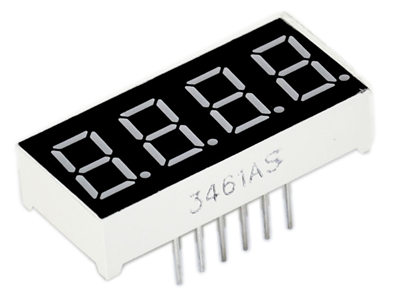
For 4-digit displays, there are 12 pins in total.
When you place the decimal point downward (see below photo position), the pin on the lower left part is referred to 1, the upper left part 12.

Manual for LED segment display:

2)Connection for V4.0:

Connection for 2560 R3:

3)Sample program
//////////////////////////////////////////////////////////
// display 1234
// select pin for cathode
int a = 1;
int b = 2;
int c = 3;
int d = 4;
int e = 5;
int f = 6;
int g = 7;
int dp = 8;
// select pin for anode
int d4 = 9;
int d3 = 10;
int d2 = 11;
int d1 = 12;
// set variable
long n = 1230;
int x = 100;
int del = 55; // fine adjustment for clock
void setup()
{
pinMode(d1, OUTPUT);
pinMode(d2, OUTPUT);
pinMode(d3, OUTPUT);
pinMode(d4, OUTPUT);
pinMode(a, OUTPUT);
pinMode(b, OUTPUT);
pinMode(c, OUTPUT);
pinMode(d, OUTPUT);
pinMode(e, OUTPUT);
pinMode(f, OUTPUT);
pinMode(g, OUTPUT);
pinMode(dp, OUTPUT);
}
/////////////////////////////////////////////////////////////
void loop()
{
Display(1, 1);
Display(2, 2);
Display(3, 3);
Display(4, 4);
}
///////////////////////////////////////////////////////////////
void WeiXuan(unsigned char n)//
{
switch(n)
{
case 1:
digitalWrite(d1,LOW);
digitalWrite(d2, HIGH);
digitalWrite(d3, HIGH);
digitalWrite(d4, HIGH);
break;
case 2:
digitalWrite(d1, HIGH);
digitalWrite(d2, LOW);
digitalWrite(d3, HIGH);
digitalWrite(d4, HIGH);
break;
case 3:
digitalWrite(d1,HIGH);
digitalWrite(d2, HIGH);
digitalWrite(d3, LOW);
digitalWrite(d4, HIGH);
break;
case 4:
digitalWrite(d1, HIGH);
digitalWrite(d2, HIGH);
digitalWrite(d3, HIGH);
digitalWrite(d4, LOW);
break;
default :
digitalWrite(d1, HIGH);
digitalWrite(d2, HIGH);
digitalWrite(d3, HIGH);
digitalWrite(d4, HIGH);
break;
}
}
void Num_0()
{
digitalWrite(a, HIGH);
digitalWrite(b, HIGH);
digitalWrite(c, HIGH);
digitalWrite(d, HIGH);
digitalWrite(e, HIGH);
digitalWrite(f, HIGH);
digitalWrite(g, LOW);
digitalWrite(dp,LOW);
}
void Num_1()
{
digitalWrite(a, LOW);
digitalWrite(b, HIGH);
digitalWrite(c, HIGH);
digitalWrite(d, LOW);
digitalWrite(e, LOW);
digitalWrite(f, LOW);
digitalWrite(g, LOW);
digitalWrite(dp,LOW);
}
void Num_2()
{
digitalWrite(a, HIGH);
digitalWrite(b, HIGH);
digitalWrite(c, LOW);
digitalWrite(d, HIGH);
digitalWrite(e, HIGH);
digitalWrite(f, LOW);
digitalWrite(g, HIGH);
digitalWrite(dp,LOW);
}
void Num_3()
{
digitalWrite(a, HIGH);
digitalWrite(b, HIGH);
digitalWrite(c, HIGH);
digitalWrite(d, HIGH);
digitalWrite(e, LOW);
digitalWrite(f, LOW);
digitalWrite(g, HIGH);
digitalWrite(dp,LOW);
}
void Num_4()
{
digitalWrite(a, LOW);
digitalWrite(b, HIGH);
digitalWrite(c, HIGH);
digitalWrite(d, LOW);
digitalWrite(e, LOW);
digitalWrite(f, HIGH);
digitalWrite(g, HIGH);
digitalWrite(dp,LOW);
}
void Num_5()
{
digitalWrite(a, HIGH);
digitalWrite(b, LOW);
digitalWrite(c, HIGH);
digitalWrite(d, HIGH);
digitalWrite(e, LOW);
digitalWrite(f, HIGH);
digitalWrite(g, HIGH);
digitalWrite(dp,LOW);
}
void Num_6()
{
digitalWrite(a, HIGH);
digitalWrite(b, LOW);
digitalWrite(c, HIGH);
digitalWrite(d, HIGH);
digitalWrite(e, HIGH);
digitalWrite(f, HIGH);
digitalWrite(g, HIGH);
digitalWrite(dp,LOW);
}
void Num_7()
{
digitalWrite(a, HIGH);
digitalWrite(b, HIGH);
digitalWrite(c, HIGH);
digitalWrite(d, LOW);
digitalWrite(e, LOW);
digitalWrite(f, LOW);
digitalWrite(g, LOW);
digitalWrite(dp,LOW);
}
void Num_8()
{
digitalWrite(a, HIGH);
digitalWrite(b, HIGH);
digitalWrite(c, HIGH);
digitalWrite(d, HIGH);
digitalWrite(e, HIGH);
digitalWrite(f, HIGH);
digitalWrite(g, HIGH);
digitalWrite(dp,LOW);
}
void Num_9()
{
digitalWrite(a, HIGH);
digitalWrite(b, HIGH);
digitalWrite(c, HIGH);
digitalWrite(d, HIGH);
digitalWrite(e, LOW);
digitalWrite(f, HIGH);
digitalWrite(g, HIGH);
digitalWrite(dp,LOW);
}
void Clear() // clear the screen
{
digitalWrite(a, LOW);
digitalWrite(b, LOW);
digitalWrite(c, LOW);
digitalWrite(d, LOW);
digitalWrite(e, LOW);
digitalWrite(f, LOW);
digitalWrite(g, LOW);
digitalWrite(dp,LOW);
}
void pickNumber(unsigned char n)// select number
{
switch(n)
{
case 0:Num_0();
break;
case 1:Num_1();
break;
case 2:Num_2();
break;
case 3:Num_3();
break;
case 4:Num_4();
break;
case 5:Num_5();
break;
case 6:Num_6();
break;
case 7:Num_7();
break;
case 8:Num_8();
break;
case 9:Num_9();
break;
default:Clear();
break;
}
}
void Display(unsigned char x, unsigned char Number)// take x as coordinate and display number
{
WeiXuan(x);
pickNumber(Number);
delay(1);
Clear() ; // clear the screen
}
//////////////////////////////////////////////////////////
4)Result
Download the above code to the V4.0 Board or MEGA 2650 Board and see the result.
The experiment result displays 1234 on the LED display.
Note: if it’s not displaying correctly, check the wiring.
Thank you.
Project 18: 8*8 LED matrix
1)Introduction
With low-voltage scanning, LED dot-matrix displays have some advantages such as power saving, long service life, low cost, high brightness, wide angle of view, long visual range, waterproof, and numerous specifications.
LED dot-matrix displays can meet the needs of different applications and thus have a broad development prospect.
This time, we will conduct an LED dot-matrix experiment to experience its charm firsthand.
2)Hardware required
- 1 * V4.0 Board or MEGA 2650 Board
- 1 * 8x8 dot-matrix
- 8 * Resistor (220Ω)
- 1 * Breadboard
- 1 * USB cable
- 16 * Jumper wires
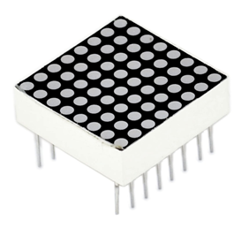
3)Circuit connection
The external view of a dot-matrix is shown as follows:

The display principle of the 8*8 dot-matrix:
The 8*8 dot-matrix is made up of sixty-four LEDs, and each LED is placed at the cross point of a row and a column.
When the electrical level of a certain row is 1 and the electrical level of a certain column is 0, the corresponding LED will light up.
If you want to light up the LED on the first dot, you should set pin 9 to high level and pin 13 to low level.
If you want to light LEDs on the first row, you should set pin 9 to high level and pins 13, 3, 4, 10, 6, 11, 15 and 16 to low level.
If you want to light the LEDs on the first column, set pin 13 to low level and pins 9, 14, 8, 12, 1, 7, 2 and 5 to high level.
Connection diagram

Connection for 2560 R3:

4)Sample program for displaying “0”
//////////////////////////////////////////////////////////
// set an array to store character of “0”
unsigned char Text[]={0x00,0x1c,0x22,0x22,0x22,0x22,0x22,0x1c};
void Draw_point(unsigned char x,unsigned char y)// point drawing function
{ clear_();
digitalWrite(x+2, HIGH);
digitalWrite(y+10, LOW);
delay(1);
}
void show_num(void)// display function, call point drawing function
{
unsigned char i,j,data;
for(i=0;i<8;i++)
{
data=Text[i];
for(j=0;j<8;j++)
{
if(data & 0x01)Draw_point(j,i);
data>>=1;
}
}
}
void setup(){
int i = 0 ;
for(i=2;i<18;i++)
{
pinMode(i, OUTPUT);
}
clear_();
}
void loop()
{ show_num();
}
void clear_(void)// clear screen
{for(int i=2;i<10;i++)
digitalWrite(i, LOW);
for(int i=0;i<8;i++)
digitalWrite(i+10, HIGH);
}
//////////////////////////////////////////////////////////
5)Test Result
Burn well the program into V4.0 Board or MEGA 2650 Board, the dot-matrix will display 0.
Note: if it’s not displaying correctly, check the wiring.
Thank you.
Project 19: Servo Control

1)Introduction
Servo motor is a position control rotary actuator.
It mainly consists of housing, circuit board, core-less motor, gear and position sensor.
2)Working principle:
The receiver or MCU outputs a signal to the servo motor. The motor has a built-in reference circuit that gives out reference signal, cycle of 20ms and width of 1.5ms. The motor compares the acquired DC bias voltage to the voltage of the potentiometer and outputs a voltage difference.
The IC on the circuit board will decide the rotating direction accordingly and drive the core-less motor. The gear then pass the force to the shaft. The sensor will determine if it has reached the commanded position according to the feedback signal.
Servomotors are used in control systems that requires to have and maintain different angles. When the motor speed is definite, the gear will cause the potentiometer to rotate. When the voltage difference reduces to zero, the motor stops. Normally, the rotation angle range is among 0-90 degrees.
Servomotor comes with many specifications. But all of them have three connection wires, distinguished by brown, red, orange colors (different brand may have different color). Brown one is for GND, red one for power positive, orange one for signal line.

The rotation angle of the servo motor is controlled by regulating the duty cycle of the PWM(Pulse-Width Modulation) signal.
The standard cycle of the PWM signal is fixed at 20ms (50 Hz), and the pulse width is distributed between 1ms-2ms. The width corresponds the rotation angle from 0° to 90°.
But note that for different brand motor, the same signal may have different rotation angle.

After some basic knowledge, let's learn how to control a servomotor.
In this experiment, you only need a servomotor and several jumper wires.
3)Hardware required
- Servo motor*1
- Breadboard jumper wire* 3
4)Connection & Sample program
There are two ways to control a servomotor with Arduino.
One is to use a common digital sensor port of Arduino to produce square wave with different duty cycle to simulate PWM signal and use that signal to control the position of the motor.
Another way is to directly use the Servo function of the Arduino to control the motor. In this way, the program will be easier but it can only control two-contact motor because of the servo function, only digital pin 9 and 10 can be used.
The Arduino drive capacity is limited. So if you need to control more than one motor, you will need external power.
Method 1:
Connection for V4.0:

Connection for 2560 R3:

Connect the signal line of motor to digital pin 9.
Compile a program to control the motor to rotate to the commanded angle, and display the angle on the monitor.
5)Sample program
Sample program A:
//////////////////////////////////////////////////////////
int servopin=9;// select digital pin 9 for servomotor signal line
int myangle;// initialize angle variable
int pulsewidth;// initialize width variable
int val;
void servopulse(int servopin,int myangle)// define a servo pulse function
{
pulsewidth=(myangle*11)+500;// convert angle to 500-2480 pulse width
digitalWrite(servopin,HIGH);// set the level of servo pin as “high”
delayMicroseconds(pulsewidth);// delay microsecond of pulse width
digitalWrite(servopin,LOW);// set the level of servo pin as “low”
delay(20-pulsewidth/1000);
}
void setup()
{
pinMode(servopin,OUTPUT);// set servo pin as “output”
Serial.begin(9600);// connect to serial port, set baud rate at “9600”
Serial.println("servo=o_seral_simple ready" ) ;
}
void loop()// convert number 0 to 9 to corresponding 0-180 degree angle, LED blinks corresponding number of time
{
val=Serial.read();// read serial port value
if(val>='0'&&val<='9')
{
val=val-'0';// convert characteristic quantity to numerical variable
val=val*(180/9);// convert number to angle
Serial.print("moving servo to ");
Serial.print(val,DEC);
Serial.println();
for(int i=0;i<=50;i++) // giving the servo time to rotate to commanded position
{
servopulse(servopin,val);// use the pulse function
}
}
}
//////////////////////////////////////////////////////////
Method 2:
Let's first take a look at the Arduino built-in servo function and some of its common statements.
1. attach(interface)——select pin for servo, can only use pin 9 or 10.
2. write(angle)——used to control the rotation angle of the servo, can set the angle among 0 degree to 180 degree.
3. read()——used to read the angle of the servo, consider it a function to read the value in the write() function.
4. attached()——determine whether the parameter of the servo is sent to the servo pin.
5. detach()—— disconnect the servo and the pin, and the pin(digital pin 9 or 10) can be used for PWM port.
Note: the written form of the above statements are "servo variable name. specific statement ()", e.g. myservo. Attach (9).
Still, connect the signal line of servo to pin 9. Please refer to the connection diagram mentioned above.
Sample program B:
Please remember to place the Servo.h library into your arduino libraries directory.
//////////////////////////////////////////////////////////
#include <Servo.h>
/*define a header file. Special attention here, you can call the servo function directly from Arduino's software menu bar Sketch>Importlibrary>Servo, or input #include <Servo.h>. Make sure there is a space between #include and <Servo.h>. Otherwise, it will cause compile error. */
Servo myservo;// define servo variable name
void setup()
{
myservo.attach(9);// select servo pin(9 or 10)
}
void loop()
{
myservo.write(90);// set rotation angle of the motor
}
//////////////////////////////////////////////////////////
Above are the two methods to control the servo. You can choose either one according to your liking or actual need.