Description

The processor core of the Mega 2560 R3 Board is ATMEGA2560-16AU, which is fully compatible with ARDUINO MEGA 2560 REV3. It comes with 54 digital input/output pins (15 of which can be used as PWM output), 16 analog inputs, 4 channels of serial communication, a 16MHz crystal
oscillator, a USB port, a power interface, an ICSP interface, and a reset button.
Among them, ICSP can burn firmware for ATMEGA2560-16AU. Since we have burned the firmware for this chip before it go out, so it is generally not used. When in use, we power the board through the USB cable, external DC power supply (DC 7-12V), or the Vin GND (DC 7-12V).
Parameters
- Microcontroller: ATMEGA2560-16AU
- Operating voltage: 5V
- Input voltage (recommended) : DC7-12V
- Digital I/O pin: 54(D0-D53)
- PWM digital I/O pin: 15(D2-D13 D44-D46)
- Analog input pin: 16(A0-A15)
- Dc current per I/O pin: 20 mA
- 3.3V pin DC current: 50 mA
- Flash memory: 256 KB, 8 KB of which is used by the BootLoader
- SRAM: 8 KB
- EEPROM: 4KB
- Clock speed: 16 MHz
- LED BUILTIN: D13
- Development board size: 101.6MM×53.2MM×12MM
- Development board weight: 30.6G
- Operating temperature: 0℃~50℃

Pin-Out


Special Interfaces
Serial communication ports (four channels) :
Serial (D0 is RX0, D1 is TX0), Serial 1 (D19 is RX1, D18 is TX1); Serial 2 (D17 is RX2, D16 is TX2); Serial 3 (D15 is RX3, D14 is TX3), where D0 and D1 are connected to the ATMEGA16U2-MU
USB-to-serial chip.
PWM interface (PWM) : D2-D13 and D44-D46
External interrupt interfaces: D2(interrupt 0), D3(interrupt 1), D21(interrupt 2), D20(interrupt 3), D19 (interrupt 4), D18 (interrupt 5)
SPI communication interface: D53 is SS, D51 is MOSI, D50 is MISO, D52 is SCK
IIC communication ports: D20 is SDA, D21 is SCL
Product Guide
Download Arduino IDE(WIN10/MAC)
First of all, we need to download and install the Arduino IDE.
You can download Arduino IDE at:
https://www.arduino.cc/en/software/
Choose the version compatible with your computer system.

Download the latest IDE version 2.3.4

After that, install the software.

Remember the installation path to make sure you can find the file next time. Click Install.

The Arduino IED is downloaded and installed here.
Download USB driver
Next, download the CH340 driver. Driver download:
https://www.wch.cn/downloads/category/67.html
First, choose the same chip model as your board.
Then, download the driver according to your computer system.

Windows Driver
Select the Windows version of the driver, click to download, and then find the download icon in the upper right corner to open the downloaded file.

Then click install.

Then check to see if the driver installation is successful. After connecting the control board to your computer by a USB cable, open the Device Manager.

Open the device manager.

If you see a yellow mark, try re-installing or changing to another interface.

The following port without a yellow mark means that the driver is installed.

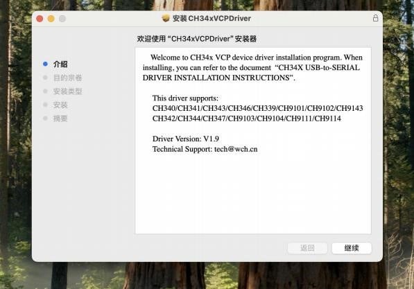
Mac Driver

After opening the installation package, we get these three files. Put the three files in one folder please! Then click the file suffix PKG to install it.

Install it. Still remember the installation path!

Burn Code on Arduino IDE
Click Arduino IDE:

and connect it to the development board and COM port. Be sure to select the correct development board, otherwise it fails to connect!

Enter the name of the board, select the corresponding board model, select the port, and click OK.

Then create a Script. You can press Ctrl+N or click "New Script" in the top left icon. You will see the following interface:

Copy and paste the following code inside. Please delete its own content.
int val; //set variable

int ledpin=13; //set led pin to 13

voidsetup (){

 Serial.begin (9600); //set baud rate

 pinMode (ledpin,OUTPUT); //set  pin mode

}


voidloop ()
 {

  val=Serial.read (); //assign serial values if (val=='R')//determine the serial value
  {

   digitalWrite (ledpin,HIGH); // light on

   delay (500); //delay 500 ms

   digitalWrite (ledpin,LOW); // light out

   delay (500); //delay 500 ms

   Serial.println ("Hello World!"); //serial outputs Hello World!

  }

}
After that, let's compile and burn codes on it. First click the Check icon to see prompts and show compiling results. If no error is reported in the "Output" area, you can click the arrow icon to proceed.

Look at the code functionality.
Ctrl+Shift+M or open the Serial Monitor to check that the code baud rate is consistent
with the software baud rate. Type a letter R into it and press Enter to display "Hello World".

At the same time, the onboard LED will also flash. Congratulations on your successful journey as a programmer!

Troubleshooting
Fails to Connect to Serial Port
- Check whether the driver is installed successfully. If no, reinstall the CH340 driver.
- See if the type-c interface and data cable can be replaced, or the computer interface can be re-plugged.
Fails to Burn Code
- Check whether the development board and port are selected correctly. If not, select the board model and port again.
- Check if the code is correct. Copy and paste the text code into it.
- Check whether the port is loose. Reinsert the port.
- Close the software and restart the computer.