This guide will give you an overview of the anatomy of a computer motherboard. Looking at a motherboard for the first time could leave you with several questions.
This quick guide seeks to identify and explain each of the key parts of a typical motherboard. This article references an ASUS B850-PLUS TUF Gaming Wi-fi Motherboard however the general design of most motherboards is very similar.
Internal
CPU Socket
Let's begin with the CPU Socket - where the processor goes. Typically, the CPU will be from one of two manufacturers: Intel or AMD. You can tell what processors are compatible by checking the socket type. This board has an AM5 socket which fits most current AMD processors:

Ram
Next, we move to the memory or RAM slots. Modern memory slots will feature one side with a clip that is used to hold the memory stick in place. The other side will be rigid to hold the stick in place but allow the memory stick to be pressed into the slot without the need to have a second clip found in older motherboards:

Power Connectors
There are two main power connectors on a motherboard. All motherboards, much like this B850, will have a motherboard power port that uses a 20+4pin configuration. Modern power supplies will usually have this already set up for the full 24pin setup. Depending on the computer, they can run anywhere from 20pin to as little as 11pin for most prebuilt towers, such as Lenovo or Dell.
For CPU power, it will typically be one 8-pin connector. If your board came with two connectors like the one in the example, use the one on the Right, you only need the one on the Left if you plan on Overclocking:

PCIe slots
Now we will look at the PCIe slots - referred to as PCI Express slots. Most motherboards will have multiple slots. This first image highlights the PCIe 16x slots (Graphic cards are the most common expansion cards placed in these slots):
PCIe x 16

PCIe x 1
The second image here highlights the PCIe 1x slots (you'll typically connect things like USB cards, sound cards, or Wi-fi cards to these ports):

Front Panel Headers
Here we see the front panel headers. This is where the USB ports and buttons on the front of the case are normally connected to the motherboard. Most of them will be on the bottom of the board, but if the board supports USB 3.0 or higher, you will see the header below or to the side of the motherboard power pins in most builds:

Sata Ports
While internal storage in computers is slowly shifting to M.2 drives, Sata drives are still widely used, providing relatively low price per TB compared to M.2. If you decide to install a Sata drive (3.5 " or 2.5" internal Hard Drives, 2.5" SSD Solid State Drives, and internal Optical Drives.), your motherboard should have plenty of ports available:

M.2 Ports
As discussed above, over the last few years, internal storage has been making a shift from Sata drives to the newer M.2 platform, while a bit pricier, these drives are significantly faster than even Sata III SSD drives. Your motherboard will likely have more than one M.2 port available, typically these days they come with a heat sync pre-installed that you first need to remove to access the port:

Fan and Pump Headers
Your motherboard will have several connectors to power your case fans as well as a Pump if you have a Liquid cooler instead of air. All motherboards have 4 pin headers for these, if the connector on your fan or pump has 3 pins, it can still be used, just line up the notch on top of the plug with the notch on the header:

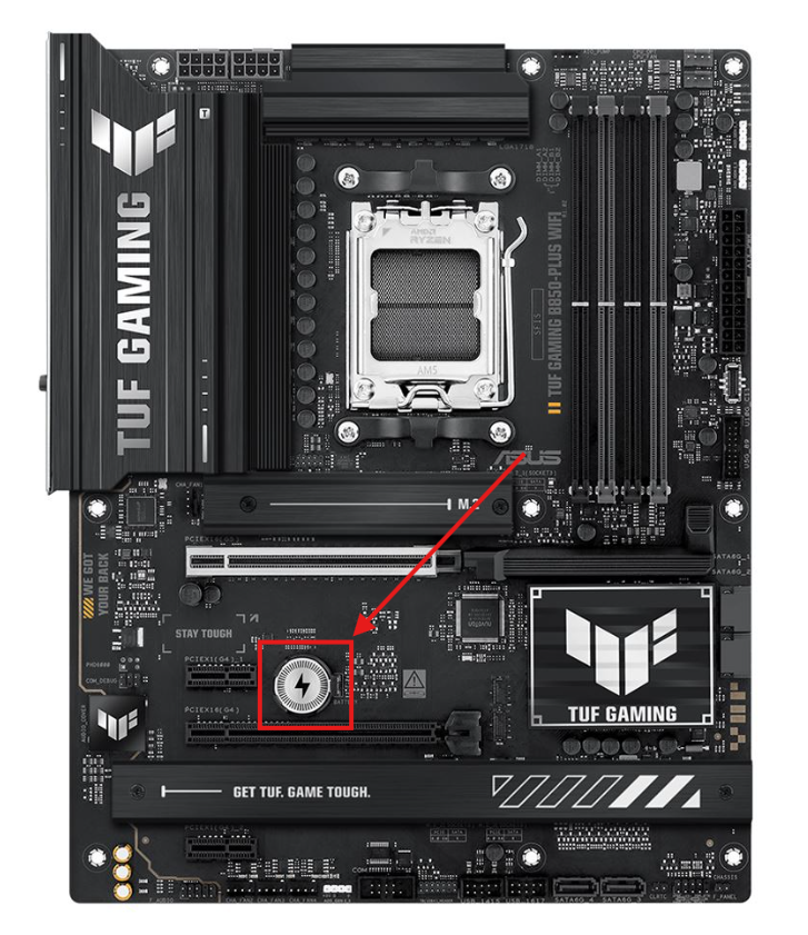
Cmos Battery
The Cmos battery is in charge of keeping a slight current of power to the Memory on your Bios, if you need to reset your Bios settings and you are unable to Access the Bios, you can unplug your computer from power and disconnect this battery, leaving it that way for about 5 min:
RGB Headers
Depending on your board, it may have RGB headers to help synchronize and control the lighting using software that can typically be downloaded from your motherboards downloads page:

External I/O Panel
Finally, let’s look at the I/O Panel - Input and Output connectors, where all your cables plug in to the back of the computer. The arrangement and selection of ports will vary between motherboards.
Video Ports
Starting on the far left, we see a couple of Video ports one labeled HDMI and the other DP (this stands for Display Port). If you do not have a dedicated graphics card, and are relying on your Processor for graphics, then these ports are where you will plug your cable from the monitor into:

USB Ports
Your motherboard will come equipped with several different kinds of USB ports. While all your USB ports can be used to plug in accessories (external drives, keyboards/mice, webcams etc) each of them has a specialty, I will break those down here:

20G USB
Also known as USB 3.2 gen 2x2, If your board has one of these ports this is going to be the fastest when it comes to things like Data Transfer, able to attain speeds of up to 20 gigabits per second (this converts to an average of 2 Gigabytes per second). If you have a drive compatible with this, it is recommended you plug it in here for the fastest speeds:

10G USB
Also known as USB 3.2 gen 2x1, if your board has these ports, they are the second fastest external port available when it comes to Data Transfer, with speeds attainable of up to 10 Gigabits per second (this converts to an average of 1 gigabyte per second). If you have a drive that is compatible, it is recommended you plug it into these ports:

5G USB
Also known as USB 3.2 gen 1x1 (formerly USB 3.0, and USB 3.1 Gen 1) these are going to be the 3rd fastest overall USB ports. They are capable of speeds up to 5 Gigabits per second (this converts to an average of 200-460 Megabytes per second) If you have a drive compatible with this, its recommended you plug it in here:

USB 2.0
These ports are best for Accessories and peripheral devices. These would be things like Keyboards, Mice, Web Cameras, or USB speakers/headsets etc. Plug those devices into these ports before you start using the high speed ones:

Bios Update USB
You may have noticed one of the 2.0 ports is labelled BIOS. Many motherboards these days support a feature called Bios Flashback (Where you can update your Bios without making it into the Bios itself), and have a port dedicated for this purpose as well as a button to initiate the procedure. See your motherboards manual for more info about how to update the Bios on your board:

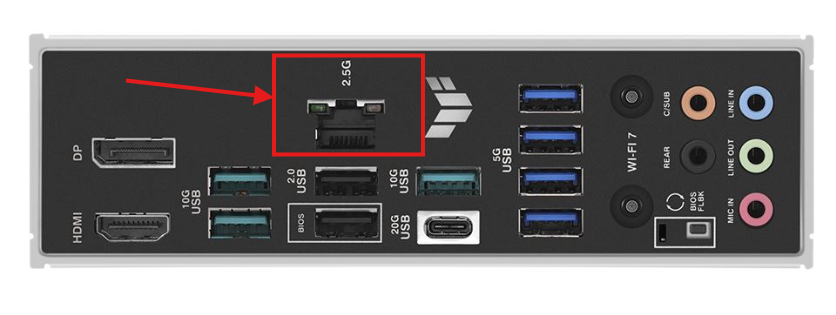
Ethernet Port
The Ethernet Port. is where the network cable would plug in to your computer. Virtually all motherboards will have one of these as desktops typically rely on a wired connection to the internet. Ethernet still provides the best network speeds and connection stability:
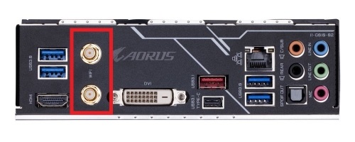
Wi-Fi Antenna Headers
Your motherboard may also have the Capability of connecting to Wi-fi and Bluetooth, you will need to connect the Antennae that came with your motherboard in order to get the best signal.
Even if you do not plan on using the Wi-fi it is still recommended that you connect the Antennae as they also help with the Bluetooth signal as well.
There are a couple different types of connectors for the Wi-fi Antennae these days, I will include examples of a couple below:
Plug in type:

Screw in type:
Audio Ports
For our last item we see the sound ports. This board has several connectors, but most of the time it comes down to what your sound setup is. Most motherboards use a standard color-coded scheme: green for audio out (speakers or headphones), and red or pink for microphones. The additional ports are for additional speakers like surround sound, a sub-woofer or related features:

You should now be equipped with enough general Knowledge about motherboards to get started!
For more specifics on your board, please check the manual that came with it, or if you do not have the manual, you can download it off the manufacturers website!